Vehiclar travel control device

a technology of travel control and control device, which is applied in the direction of distance measurement, instruments, and using reradiation, etc., can solve the problems of cost, maintenance, adjustment, and control burdens, and achieve the effect of reducing the burden of maintenance and adjustmen

Inactive Publication Date: 2004-07-15
HITACHI ASTEMO LTD
View PDF8 Cites 64 Cited by
  • Summary
  • Abstract
  • Description
  • Claims
  • Application Information

AI Technical Summary

Problems solved by technology

However, there has been the problem that, in the prior art, speed and angle must be directly measured using many different kinds of sensors in order to obtain these physical quantities, and the burdens of cost, maintenance, adjustment, and control have been great.

Method used


Image

  • Vehiclar travel control device
  • Vehiclar travel control device
  • Vehiclar travel control device

Examples


first embodiment

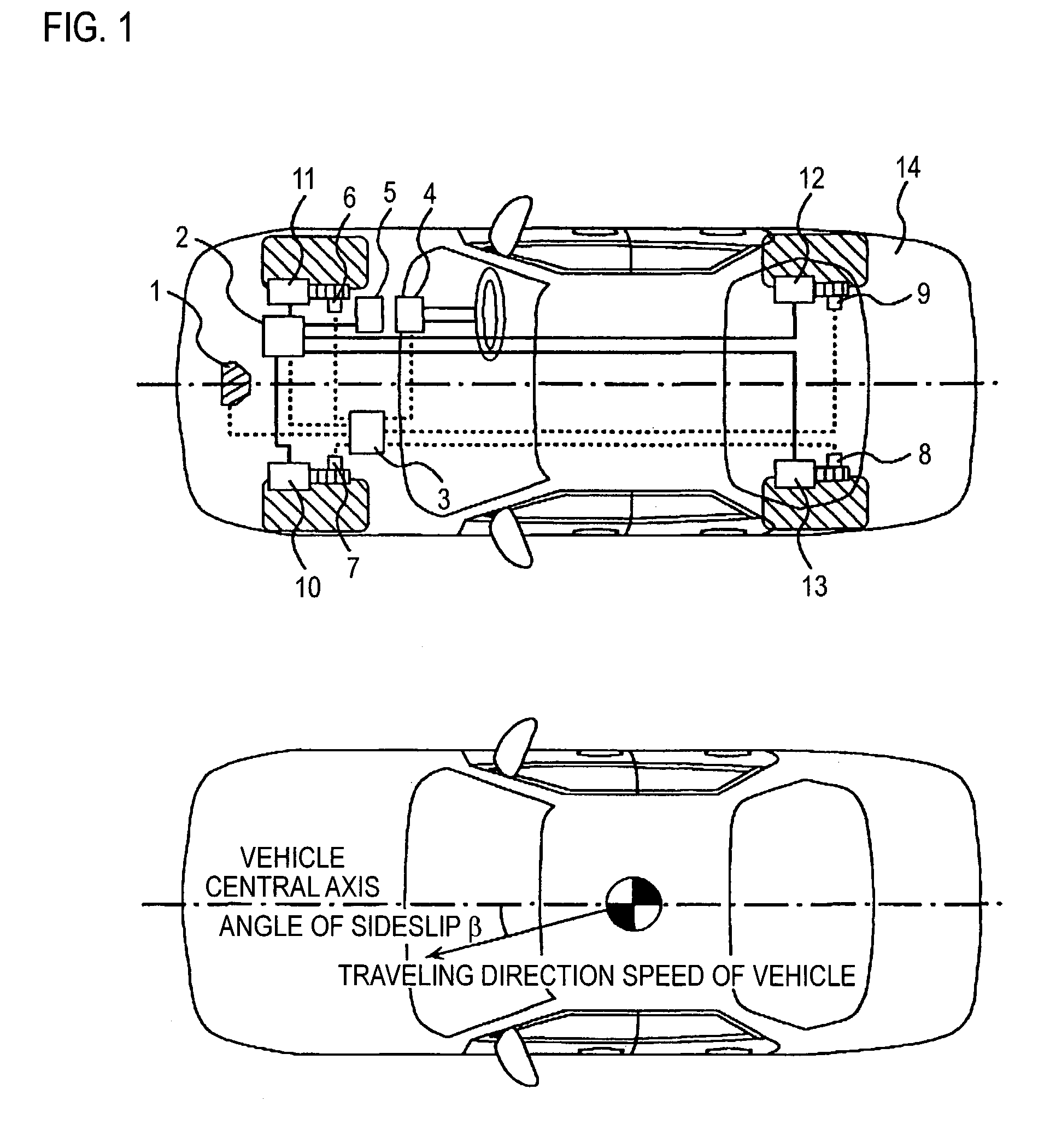
[0027] FIG. 1 illustrates, as a first embodiment, a vehicle equipped with a braking control device of the present invention. Installed in a vehicle 14 are: a ground speed sensor 1, which is a radar sensor or the like that detects relative speed with respect to a road surface; a brake unit 2 that controls braking force of each wheel, and which here is a hydraulic brake unit that controls pressure applied to hydraulic brake calipers; an electronic control unit 3 that conducts calculation processing on the basis of a signal from the sensor and controls, on the basis of the calculation result, an actuator and an actuator such as a brake unit and shock absorbers that can vary a damping coefficient; a steering angle sensor 4 that detects a steering angle; a stroke sensor 5 that detects, as a stroke, a depression amount of an accelerator pedal; wheel speed sensors 6, 7, 8 and 9 that detect wheel speeds of wheels; and brake calipers 10, 11, 12 and 13 that control the braking force.

[0028] FI...

third embodiment

[0059] FIG. 11 illustrates, as a third embodiment, a vehicle equipped with the travel control device of the present invention. Installed in the vehicle 14 are three radar sensors 16, 17 and 18, the hydraulic unit 2, the electronic control unit 3, the steering angle sensor 4, the stroke sensor 5, the wheel speed sensors 6, 7, 8 and 9, and the brake calipers 10, 11, 12 and 13. The forward speed V.sub.X, the left-right direction speed V.sub.Y, the vertical speed w, the angle of sideslip .beta., the pitch angle .theta., and the roll angle .phi. can be calculated even by using the three radar sensors 16, 17 and 18. First, the forward speed V.sub.X is calculated by equation 12. 18 V X = - v 16 sin ( - ) (Equation18)

[0060] Here, V.sub.16 is relative speed information of the radar sensor 16, and .alpha. is the mounting angle between the radar sensors and the road surface (e.g., 45 degrees). Next, the left-right direction speed V.sub.Y is calculated by equation 19. 19 V Y = v 17 sin ( + )- v...


PUM


Abstract

In a vehicular control device, it is necessary to measure or calculate six physical quantities-forward-reverse speed, left-right speed, vertical speed, pitch angle, roll angle, and angle of sideslip-representing vehicular movement and to control the braking force of each wheel and/or the damping coefficient of each suspension shock absorber in order to further shorten braking distance particularly at the time of braking and to prevent spin at that time. In this case, it is necessary to furnish sensors to measure speed and angle directly. In the present invention, four radar sensors are used in order to directly measure the forward-reverse speed and the left-right speed. Also, the vertical speed, the pitch angle, the roll angle, and the angle of sideslip are indirectly measured from the output of the radar sensors. By using three or four radar sensors, six physical quantities-the forward speed, the left-right direction speed, the vertical speed, the angle of sideslip, the pitch angle, and the roll angle-can be measured. Also, by using two radar sensors, three physical quantities-the forward speed, the left-right speed, and the angle of sideslip-can be measured.

Description

[0001] 1. Field of the Invention[0002] The present invention relates to a vehicular travel control device using radar sensors.[0003] 2. Description of Related Art[0004] An electric control device that is equipped with six different kinds of sensors--speed sensors, forward-reverse acceleration sensor, left-right acceleration sensor, vertical acceleration sensor, clearance sensor, and yaw rate sensor--for a total of sixteen sensors, calculates six physical quantities-forward-reverse speed, left-right speed, vertical speed, pitch angle, roll angle, and yaw angle--representing vehicular movement, and conducts control of shock absorbers is disclosed in JP-A-2001-47832.[0005] In a vehicular control device, it is necessary to measure or calculate six physical quantities-forward-reverse speed, left-right speed, vertical speed, pitch angle, roll angle, and angle of sideslip--representing vehicular movement and to control the braking force of each wheel and / or the damping coefficient of each ...

Claims


Application Information

Patent Timeline
Patent Type & Authority Applications(United States)
IPC IPC(8): B60G17/016B60G17/015B60G17/019B60G17/0195B60R16/02B60T8/172B60T8/1755G01S13/36G01S13/86G01S13/93
CPCB60G17/016G01S13/874B60G17/0195B60G2400/0511B60G2400/0512B60G2400/0513B60G2400/204B60G2400/2042B60G2400/252B60G2401/174B60G2800/702B60T8/172B60T2250/04B60W2420/00B60W2420/52G01S13/36G01S2013/9346G01S13/60B60G17/019G01S2013/93185
Inventor KURAGAKI, SATORUYOSHIKAWA, TOKUJIIZUMI, SHIHOKURODA, HIROSHIKOJIMA, TAKAOMINOWA, TOSHIMICHIMANAKA, TOSHIOUEKI, NOBUYUKITAKANO, KAZUAKI
Owner HITACHI ASTEMO LTD
Why Eureka
Try Eureka