Medical image processing system

a medical image and processing system technology, applied in the field of medical image processing system, can solve problems such as large communication load of the network, inability to accurately diagnose the patient,

Inactive Publication Date: 2004-07-29
KONICA MINOLTA INC
View PDF8 Cites 28 Cited by
  • Summary
  • Abstract
  • Description
  • Claims
  • Application Information

AI Technical Summary

Benefits of technology

[0019] According to the first aspect of the present invention, the communication load of the communication network is monitored, and the image transmission time of the medical image data for transmitting from the medical image generating apparatus to the suspicious region candidate detecting apparatus is set in the time zone in which the communication load is small on the basis of the monitoring result. Consequently, the communication load of the communication network can be reduced, and thereby improvement of image processing efficiency of the medical image processing system can be achieved.
[0091] According to the invention, the medical image data about which the detection of the suspicious region candidate has ended and the detection result of the suspicious region candidates are outputted to a film or a recording medium or are display-outputted by the output apparatus. Consequently, the detection result of the suspicious region candidate can be easily confirmed.

Problems solved by technology

However, because the detection of the suspicious regions depends on the skill of the doctor who performs the interpretation of the radiograph (hereinafter referred to as a "radiograph interpreting doctor"), there is some possibility that some differences are caused in the detection results of the suspicious regions with radiograph interpreting doctors.
Moreover, in case of dealing with a large quantity of medical images at a mass examination or the like, the operations of interpreting radiographs are a considerable burden for a radiograph interpreting doctor.
However, because in the above-described medical image processing system, a large capacity of data such as medical image data or the like is transmitted and received between each apparatus through the communication networks, the communication loads of the networks become large in some time zones, and then a long time is sometimes needed for executing transmission and reception.
Consequently, the loads of the networks still more become larger, and the increase of the loads is a cause of large delay of processing of medical image data in the whole medical image processing system.
Moreover, when the interpretation of a radiograph of a medical image can be performed in a suspicious region candidate detecting apparatus, there is some possibility that the execution of the detection processing of suspicious region candidates while a radiograph interpreting doctor is interpreting a radiograph makes the operation of the interpretation of the radiograph slow to disturb the operation of the interpretation of the radiograph.
Therefore, nothing but cost to communication equipment of high capacity is required, so that it cannot be said that it is sufficient from viewpoint of making the whole network more efficient.

Method used


Image

  • Medical image processing system
  • Medical image processing system
  • Medical image processing system

Examples


first embodiment

[0110] With respect to a first embodiment, descriptions will be given to an example in which a medical image generating apparatus will monitor the communication load of a communication network N and medical image data being an object of detection of suspicious region candidates will be transmitted to a suspicious region candidate detecting apparatus in a time zone such that the communication load will be small on the basis of the monitoring results.

[0111] First, the configuration of the first embodiment will be described.

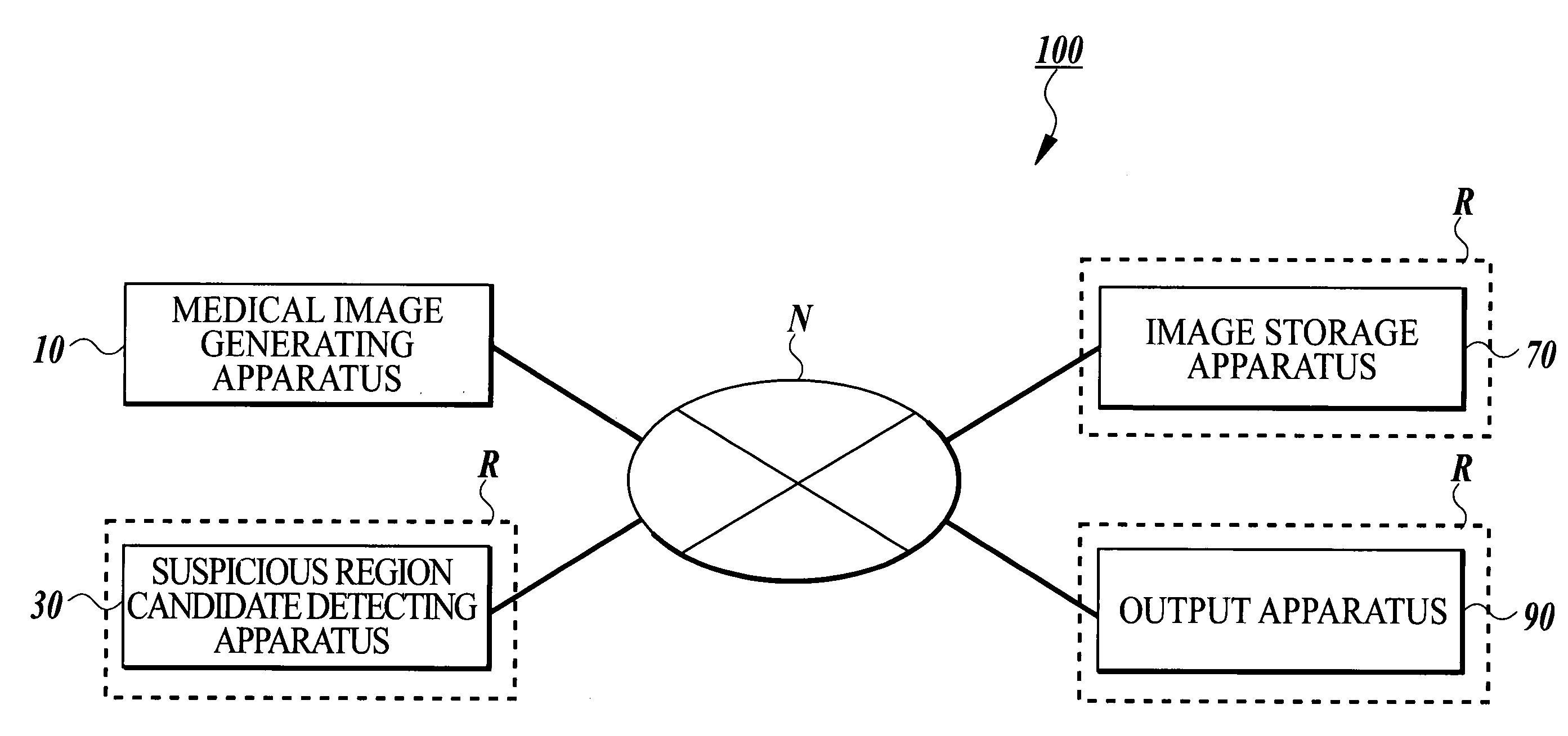
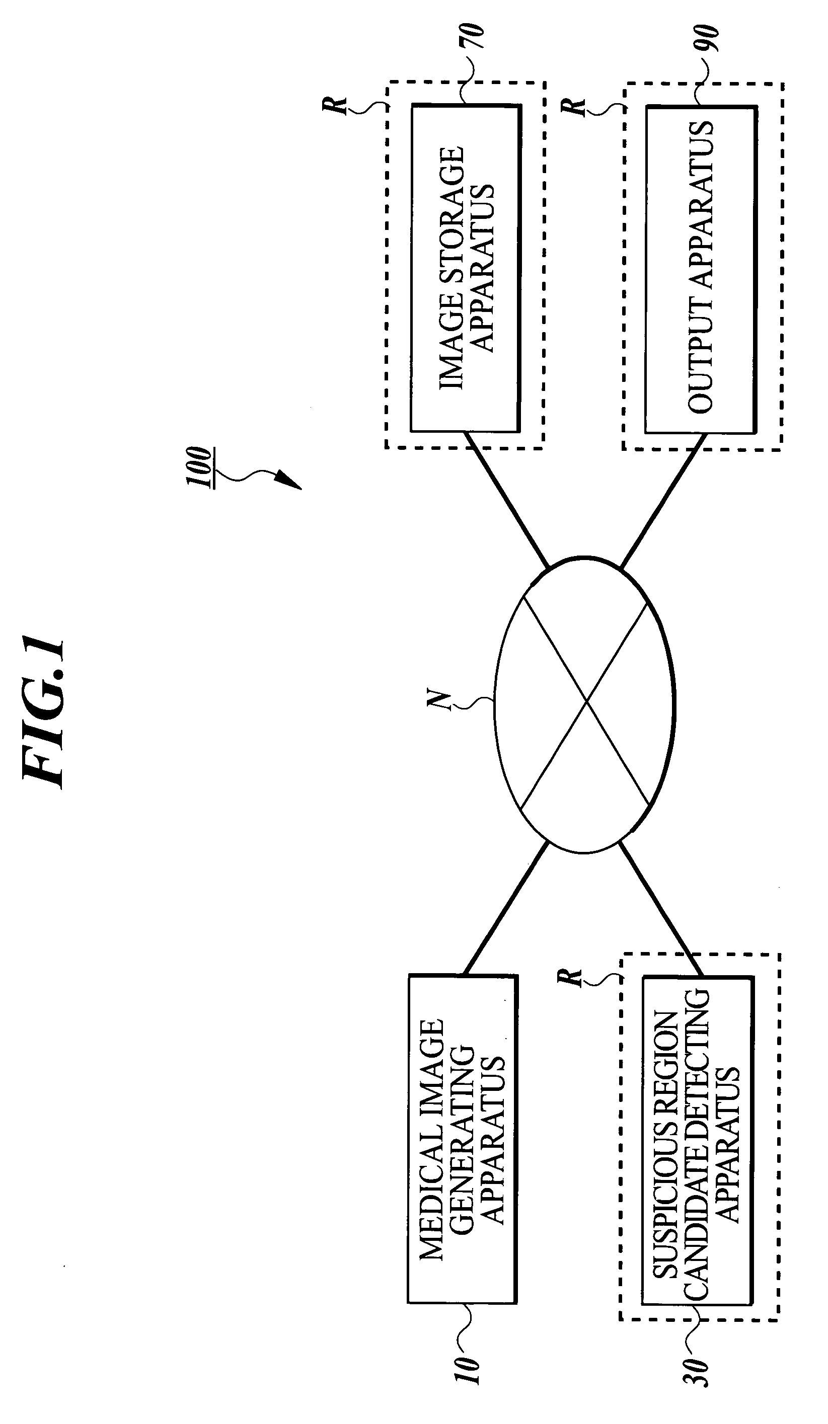
[0112] FIG. 1 shows the system configuration of a medical image processing system 100 of the first embodiment.

[0113] As shown in FIG. 1, the medical image processing system 100 comprises a medical image generating apparatus 10, a suspicious region candidate detecting apparatus 30, an image storage apparatus 70 and an output apparatus 90. Each apparatus is connected to each other so that transmission and reception of information can be performed through a communicati...

second embodiment

[0191] With respect to a second embodiment, descriptions will be given to an example in which a suspicious region candidate detecting apparatus will monitor the communication load of a communication network to set a detection time of suspicious region candidates and then medical image data will be received from a medical image transmitting apparatus in a time zone in which the communication load will be small on the basis of the monitoring results of the communication load and the detection time.

[0192] First, the configuration of the second embodiment will be described.

[0193] FIG. 9 shows the system configuration of a medical image processing system 200 of the second embodiment. Incidentally, the same constituent apparatus of the medical image processing system 200 as those of the medical image processing system 100 of the first embodiment, that is, the image storage apparatus 70 and the output apparatus 90, are designated by the same reference numerals as those of the medical image...


PUM


Abstract

A medical image processing system including a medical image generating apparatus for generating medical image data of a radiographed subject; a suspicious region candidate detecting apparatus for detecting a suspicious region candidate from the generated medical image data, the detecting apparatus being connected with the generating apparatus through a communication network; a network monitoring section for monitoring a communication load of the communication network; and a time setting section for setting an image transmission time for transmitting the medical image data from the generating apparatus to the detecting apparatus on the basis of a monitoring result of the communication load. The generating apparatus transmits the medical image data to the detecting apparatus at the set image transmission time.

Description

[0001] 1. Field of the Invention[0002] The present invention relates to a medical image processing system and a medical image processing method.[0003] 2. Description of Related Art[0004] In the field of medical care, for example, a technique for obtaining digital medical image data by various medical image generating apparatuses such as a computer-aided radiographic image reading apparatus (hereinafter referred to as "computed radiography (CR)"), a nuclear magnetic resonance imaging apparatus (hereinafter referred to as "magnetic resonance imaging (MRI)") and the like have been developed, and thereby the electronic archiving of medical images is enabled.[0005] Then, it is generally conducted that a doctor detects the suspicious regions which look like lesion by interpreting a radiograph formed by the medical image data output on a film or a display section, and that the doctor makes a diagnosis by observing the states and the variations with time of the lesion. However, because the ...

Claims


Application Information

Patent Timeline
Patent Type & Authority Applications(United States)
IPC IPC(8): A61B5/055A61B8/00A61B6/00G06T7/00G16H30/20G16H40/67H04L29/08
CPCG06F19/321G06T7/0012H04L69/329H04L67/12H04L67/322G16H40/67G16H30/20H04L67/61
Inventor KASAI, SATOSHI
Owner KONICA MINOLTA INC
Why Eureka
Try Eureka