Color cathode lay tube and method of manufacturing the same

a technology of cathode and color, which is applied in the manufacture of photo-emissive cathodes, electric discharge tubes/lamps, electric discharge tubes, etc., can solve the problems of undeflection power increase, difficult to form the curved surface of the shadow mask, and difficult to precisely position those two electrode so as to improve the focus characteristic of electron beams over the entire screen area and improve the luminance of the entire screen

Inactive Publication Date: 2004-08-19
KK TOSHIBA
View PDF15 Cites 1 Cited by
  • Summary
  • Abstract
  • Description
  • Claims
  • Application Information

AI Technical Summary

Benefits of technology

[0020] The present invention has been made in view of the above problems and its object is to provide a color cathode ray tube and a method of manufacturing the same, which improve the focus characteristic of electron beams over the entire screen area so that the luminance of the entire screen can be improved.
[0024] According to the color cathode ray tube structured as described above, when electron beams are irradiated on the dielectric layers during operation, each dielectric layer is charged to minus and forms an electron lens which acts on the electron beams. When electron beams pass the apertures of the shadow mask, the beams pass between dielectric layers provided on both sides of each apertures, receive reaction forces from both sides by the dielectric layers, and are thereby converged toward the aperture. In this manner, the portion of the electron beams traveling toward the apertures, which conventionally collides into the shadow mask, can be converged toward the apertures so as to pass the apertures. Accordingly, the amount of electron beams which pass through the apertures increases so that the density of the electron beams which reach the phosphor screen is raised thereby improving the luminance on the screen.
[0025] Also, according to the color cathode ray tube structured as described above, the electron beams are converged by the dielectric layers provided on both sides of each aperture. Hence, it is unnecessary to provide conventional electrodes and it is also unnecessary to position those electrodes in relation to each other. Simultaneously, by adjusting the layout position, width, height, dielectric constant, and the like of each dielectric layer, the charge amount of dielectric layers and the forces of dielectric layers acting on electron beams can be adjusted, so that the focus state of electron beams can be controlled easily.
[0026] Further, the focus state of electron beams may be controlled so that the electron beams are converged in the horizontal direction and diverged in the vertical direction. With this focus state of electron beams, a problem under interference fringes called moire can be easily prevented in a shadow mask having bridge portions.
[0027] It is therefore possible to obtain a color cathode ray tube which can be manufactured easily and can attain an excellent focus state over the entire screen area.
[0028] Further, according to the method of manufacturing a color cathode ray tube according to the present invention, insulating material layers are formed on a mask base material, and thereafter, the mask base material is shaped. Hence, a shadow mask having a desired shape can be attained easily. Further, when forming the insulating material layers on the mask base material, it is possible to adjust freely the width of the insulating material layers and the position thereof relative to apertures. This enables grading the positions of the dielectric layers between the center part and the peripheral part of the shadow mask, so that the dielectric layers are provided in compliance with the focus state of the electron beams. Accordingly, it is possible to manufacture a color cathode ray tube in which an excellent focus state is obtained over the entire screen area and the luminance is improved.

Problems solved by technology

Consequently, in this case, the deflection power must be increased undesirably from the viewpoint of energy saving.
Further, improvements in luminance by a method called a focus mask have conventionally been tried although the method has not yet been put into practice.
It is difficult to position precisely those two electrodes over the entire area of the screen.
In this structure, however, it is difficult to form the curved surface of the shadow mask.
If the apertures cannot be in a stagger array, interference fringes called moire appear on the screen, so that the display quality of the screen is greatly degraded, leading to poor realization.
It is therefore difficult to vary the electrode layout between the screen center part and the peripheral part of the screen.
If this structure is used in a color cathode ray tube, it cannot be considered that an excellent convergence effect on electron beams is obtained over the entire screen.
There is a risk that a part of the electron beams deflected toward the peripheral region of the screen collides into the ridge part of the shadow mask.
As has been described above, in case of a focus mask which has conventionally been proposed, high precision is required in formation of electrodes and it is difficult to form the shadow mask surface in a desired shape.
In addition, there is a problem that the degree of freedom is low in formation of electrodes, so that control of electron beams is substantially impossible.

Method used


Image

  • Color cathode lay tube and method of manufacturing the same
  • Color cathode lay tube and method of manufacturing the same
  • Color cathode lay tube and method of manufacturing the same

Examples


Embodiment Construction

[0046] Hereinafter, a color cathode ray tube according to an embodiment of the present invention will be explained in details with reference to the drawings.

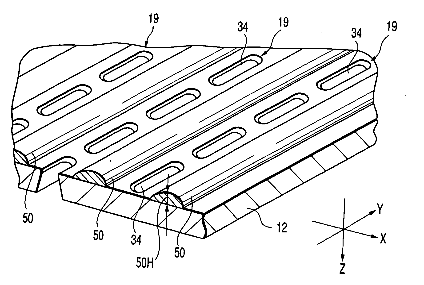
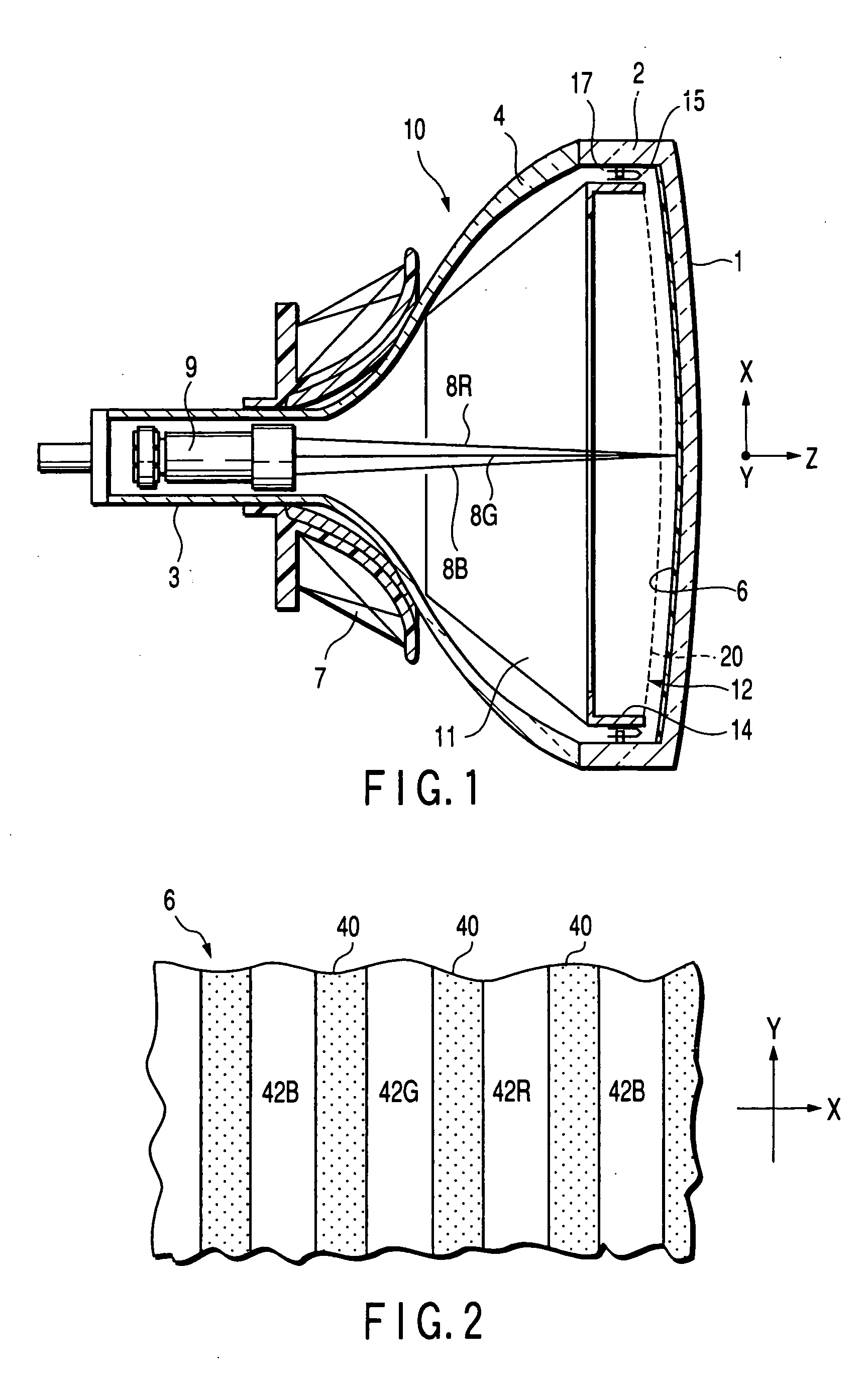
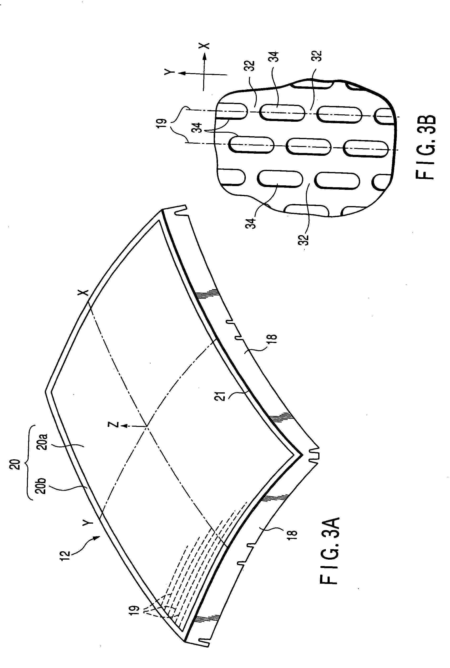
[0047] As shown in FIG. 1, the color cathode ray tube comprises a vacuum envelope 10. The vacuum envelope 10 has a panel 1, which has a skirt portion 2 at its periphery and a substantially rectangular outer surface, a funnel 4 joined to the skirt portion of the panel, and-a cylindrical neck 3 connected to a small-diameter part of the funnel.

[0048] A phosphor screen 6 is formed on the inner surface of the panel 1. A deflection yoke 7 having horizontal and vertical deflection coils are mounted on the outer circumference of the envelope from the neck 3 to the funnel 4. An electron gun 9 which emits three electron beams 8R, 8G, and 8B toward the phosphor screen 6 is provided in the neck 3. The electron gun 9 emits three electron beams 8 (B, G, and R) in the tube axis direction Z. The electron beams include a center beam 8G and paire...


PUM


Abstract

A shadow mask is arranged to face a phosphor screen formed on an inner surface of a panel. A plurality of aperture columns are formed in parallel in the shadow mask. Each aperture column includes a plurality of apertures arranged in line at a predetermined interval. On both sides of each aperture column on the surface of the shadow mask facing the electron gun, stripe-shaped dielectric layers for acting on electron beams toward the apertures are formed respectively, and extend in substantial parallel with the aperture columns. The shadow mask is manufactured in such a manner that stripe-shaped insulating material layers are formed on the surface of a mask base material facing the electron gun, the mask base material is thereafter shaped into a predetermined shape, and the insulating material layers on the shaped mask are sintered.

Description

[0001] This application is based upon and claims the benefit of priority from the prior Japanese Patent Applications No. 2001-022165, filed Jan. 30, 2001; and No. 2001-201284, filed Jul. 2, 2001, the entire contents of both of which are incorporated herein by reference.[0002] 1. Technical Field[0003] The present invention relates to a color cathode ray tube and a method of manufacturing the same.[0004] 2. Background Art[0005] In general, a color cathode ray tube is provided with a vacuum envelope including a substantially rectangular panel and a funnel. A phosphor screen is formed on the inner surface of an effective portion of the panel. A substantially rectangular shadow mask is provided in the vacuum envelope, facing the phosphor screen.[0006] In the neck of the funnel, an electron gun which emits electron beams is provided. Further, in the color cathode ray tube, three electron beams emitted from the electron gun are deflected by a deflection yoke mounted on the outside of the f...

Claims


Application Information

Patent Timeline
Patent Type & Authority Applications(United States)
IPC IPC(8): H01J9/14H01J29/07H01J29/58
CPCH01J9/142H01J9/146H01J2229/0777H01J29/58H01J29/07
Inventor TAKAHASHI, TOHRUINOUE, MASATSUGUFUKUDA, KUMIONIKAIDO, MASARUSHIOZAWA, HITOSHINAKAMURA, AKIYOSHIISHIKAWA, SATOSHI
Owner KK TOSHIBA
Why Eureka
Try Eureka