Fluid machine operable in both pump mode and motor mode and waste heat recovering system having the same

a technology of waste heat recovery and pump mode, which is applied in the direction of positive displacement liquid engines, liquid fuel engines, piston pumps, etc., can solve the problems of vapor compression refrigeration system not being operated properly, single compressor cannot be used as an expander, and high pressure gas cannot be supplied to the working chamber

Inactive Publication Date: 2004-09-23
DENSO CORP +1
View PDF10 Cites 61 Cited by
  • Summary
  • Abstract
  • Description
  • Claims
  • Application Information

AI Technical Summary

Problems solved by technology

Thus, the single compressor cannot be used as the expander.
As a result, one of the Rankine cycle and the vapor compression refrigeration system cannot be operated properly.
Thus, even in a case where a means for reversing the gas inlet and the gas outlet is provided in the above arrangement, when the compressor is operated as the expander, the high pressure gas cannot be supplied to the working chamber due to the presence of the check valve, which blocks flow of the high pressure gas into the working chamber.
As a result, the compressor cannot be used as the expander even if the means for reversing the gas inlet and the gas outlet is provided.
As a result, a rotational speed of the compressor used as the expander is reduced, and a degree of leakage of fluid per rotation of the compressor is increased to decrease an efficiency of the expander.

Method used


Image

  • Fluid machine operable in both pump mode and motor mode and waste heat recovering system having the same
  • Fluid machine operable in both pump mode and motor mode and waste heat recovering system having the same
  • Fluid machine operable in both pump mode and motor mode and waste heat recovering system having the same

Examples


first embodiment

[0041] Next, the integrated compressor / expander apparatus 10 of the first embodiment will be described.

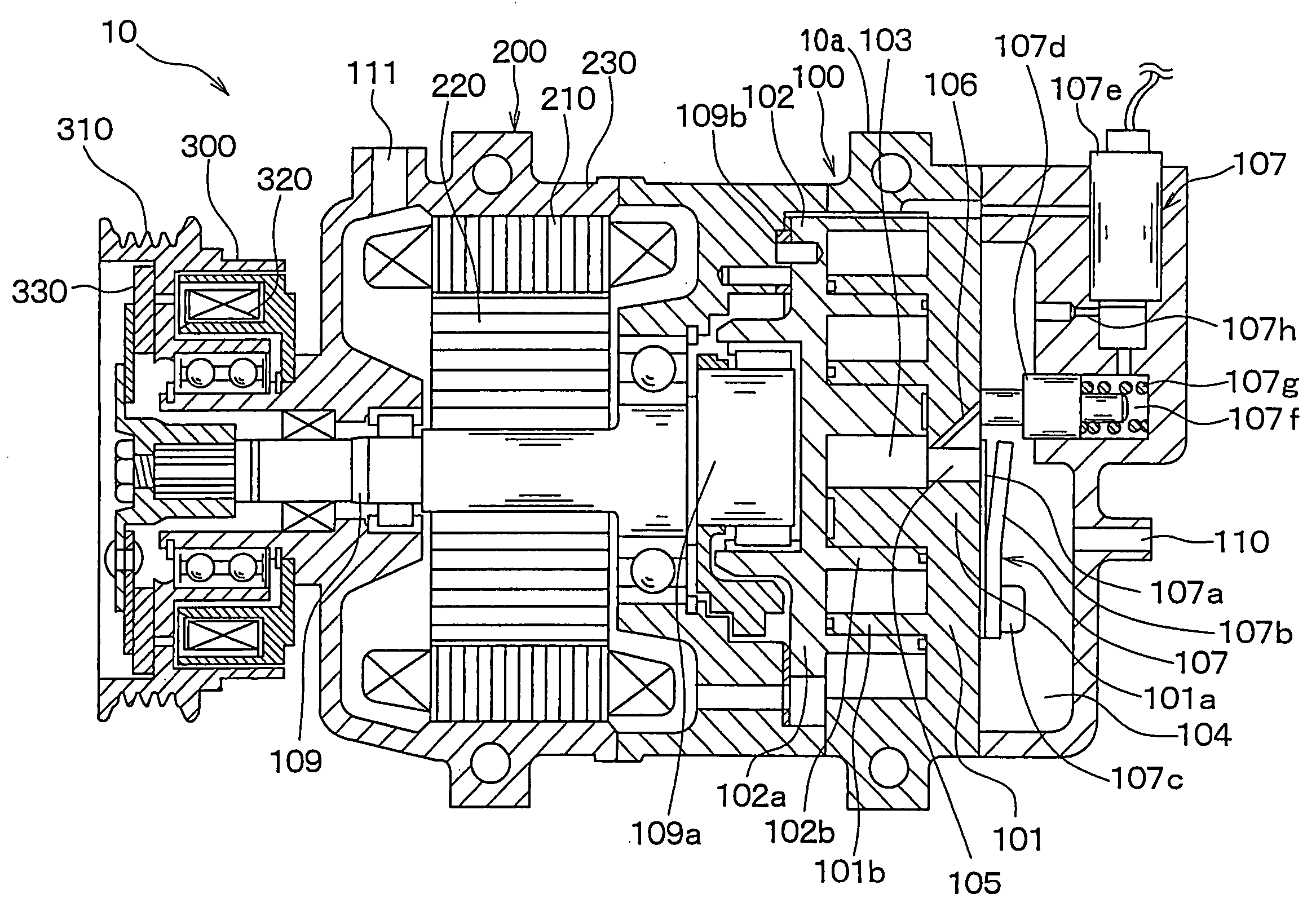
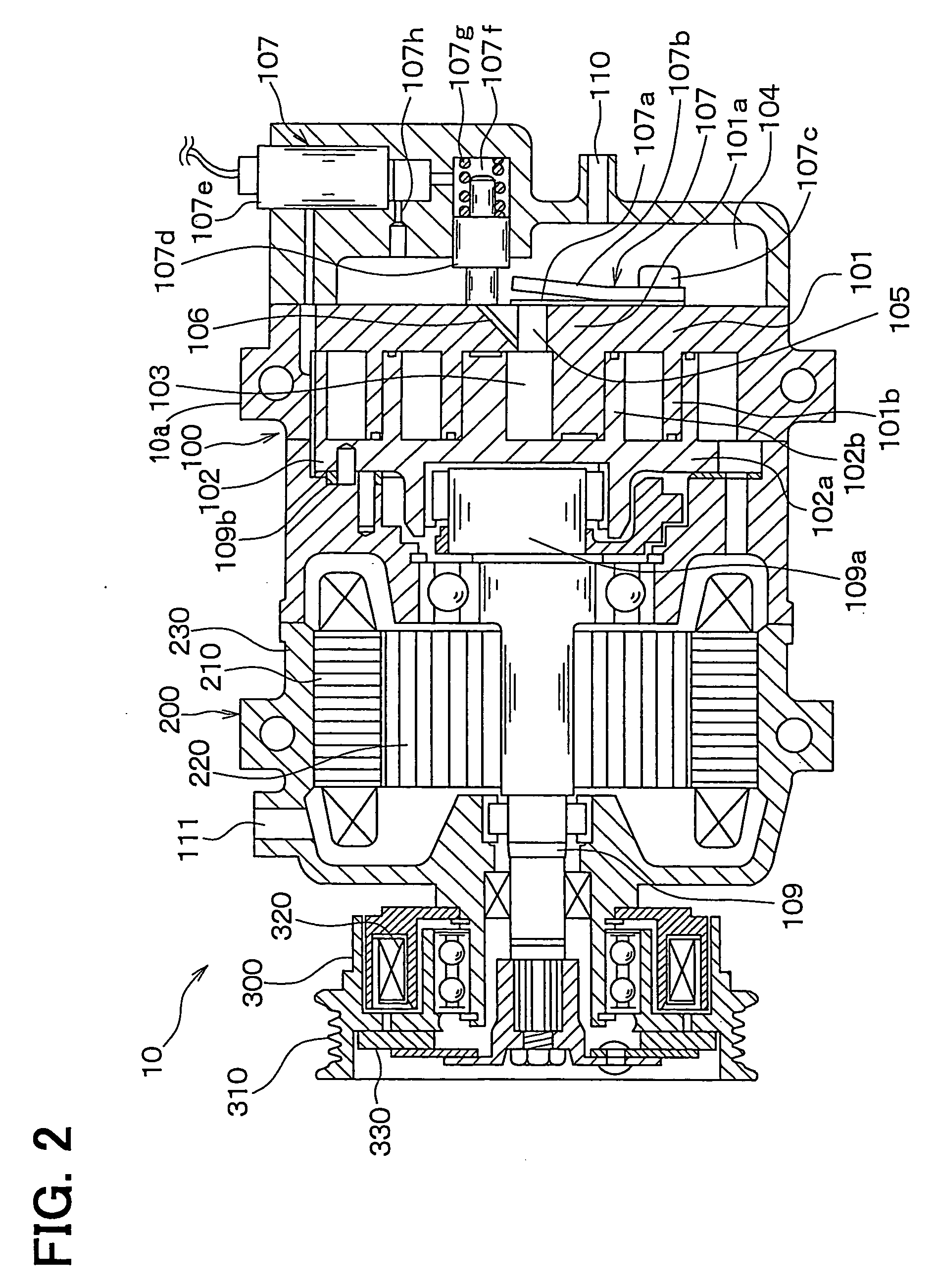
[0042] FIG. 2 is a cross sectional view of the integrated compressor / expander apparatus 10. The integrated compressor / expander apparatus 10 includes a housing 10a, a pump motor mechanism 100, a dynamo-electric machine 200 and an electromagnetic clutch 300. The housing 10a receives the pump motor mechanism 100 and the dynamo-electric machine 200. The pump motor mechanism 100 compresses or expands fluid (gas phase refrigerant in this embodiment). The dynamo-electric machine 200 is connected to a shaft 109 of the pump motor mechanism 100. The electromagnetic clutch 300 is a drive force transmission mechanism or arrangement, which enables and disables transmission of drive force from the engine (serving as an external drive source) 20 to the pump motor mechanism 100, more specifically, to the shaft 109 of the pump motor mechanism 100.

[0043] The dynamo-electric machine 200 includes a st...

second embodiment

[0082] In the first embodiment, the intake port 106 is constituted by the switching valve of the pilot type. In a second embodiment, as shown in FIG. 3, a switching solenoid valve 107i of a direct drive type, which directly opens and closes the intake port 106, is used.

third embodiment

[0083] In a third embodiment, as shown in FIG. 4, the discharge port 105 also acts as the intake port 106, and the discharge valve 107a, which includes the valve stop plate 107b, is forcefully displaced by an actuator 112 to open the discharge port 105 (intake port 106) at the time of operation in the motor mode.

[0084] The actuator 112 of the present embodiment is an actuator of a pilot type, which uses a pressure difference in a manner similar to that of the mechanism, which displaces the spool 107.

[0085] More specifically, the actuator 112 includes a piston 112a, a solenoid valve 112c, a spring 112d and a throttle 112e. The discharge valve 107a, which includes the valve stop plate 107b, is secured to the piston 112a. The solenoid valve 112c controls a pressure in a back pressure chamber 112b by controlling communication between the low pressure port 111 and the back pressure chamber 112b. The spring 112d applies spring force to the piston 112a to displace the discharge valve 107a,...


PUM


Abstract

A check valve is provided to each discharge port, which communicates between a corresponding working chamber and a high pressure chamber in an integrated compressor/expander apparatus. A valve mechanism, which is opened in a motor mode, is provided to communicate between the working chamber and the high pressure chamber.

Description

[0001] This application is based on and incorporates herein by reference Japanese Patent Application No. 2003-19139 filed on Jan 28, 2003, Japanese Patent Application No. 2003-165112 filed on Jun. 10, 2003, and Japanese Patent Application No. 2003-328284 filed on Sept. 19, 2003.[0002] 1. Field of the Invention[0003] The present invention relates to a fluid machine, which is operable in a pump mode for pressurizing and discharging fluid and is also operable in a motor mode for converting fluid pressure exerted at the time of expansion of fluid into kinetic energy and thereafter outputting the kinetic energy as mechanical energy, and also relates to a waste heat recovering system having the same.[0004] 2. Description of Related Art[0005] In a previously proposed vapor compression refrigeration system, which has a Rankine cycle, when energy is recovered through the Rankine cycle, a compressor of the vapor compression refrigeration system is used as an expander, as disclosed in, for exa...

Claims


Application Information

Patent Timeline
Patent Type & Authority Applications(United States)
IPC IPC(8): F02G5/04
CPCB60H1/3223F01C1/0215F01C20/04F01K23/065F01C20/24F04B49/24F04B53/16Y02T10/166F02G5/04B60H1/3228Y02T10/12
Inventor IWANAMI, SHIGEKIYAMANAKA, YASUSHISUZUKI, YASUSHIINABA, ATSUSHIASA, HIRONORIUNO, KEIICHIUCHIDA, KAZUHIDE
Owner DENSO CORP
Why Eureka
Try Eureka