Thermal fuse having a function of a current fuse

a technology of thermal fuse and current fuse, which is applied in the direction of relays, biochemical water/sewage treatment, plant cultivation, etc., can solve the problems of battery entering dangerous state, disadvantageous to a portable apparatus use, and inability to use as a current fus

Inactive Publication Date: 2004-10-07
UCHIHASHI ESTEC
View PDF4 Cites 15 Cited by
  • Summary
  • Abstract
  • Description
  • Claims
  • Application Information

AI Technical Summary

Problems solved by technology

In a secondary battery, an overcurrent of about 2 to 10 A sometimes flows for a long time period (about 1,000 seconds) , thereby causing the battery to enter a dangerous state.
Therefore, the system fails to fulfill the request of miniaturization of a battery pack, and hence is disadvantageous t

Method used


Image

  • Thermal fuse having a function of a current fuse
  • Thermal fuse having a function of a current fuse
  • Thermal fuse having a function of a current fuse

Examples


example

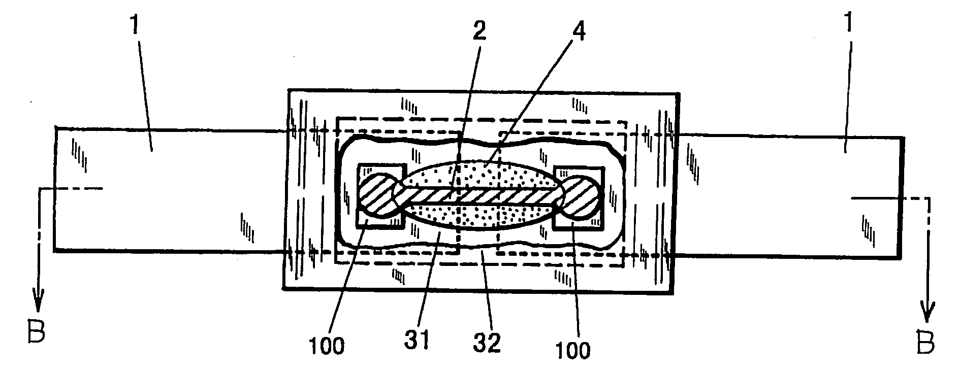
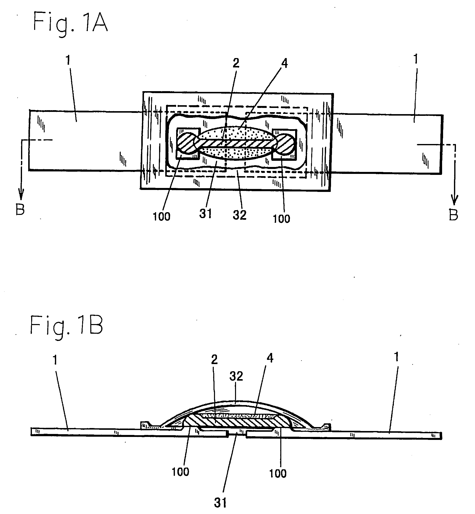
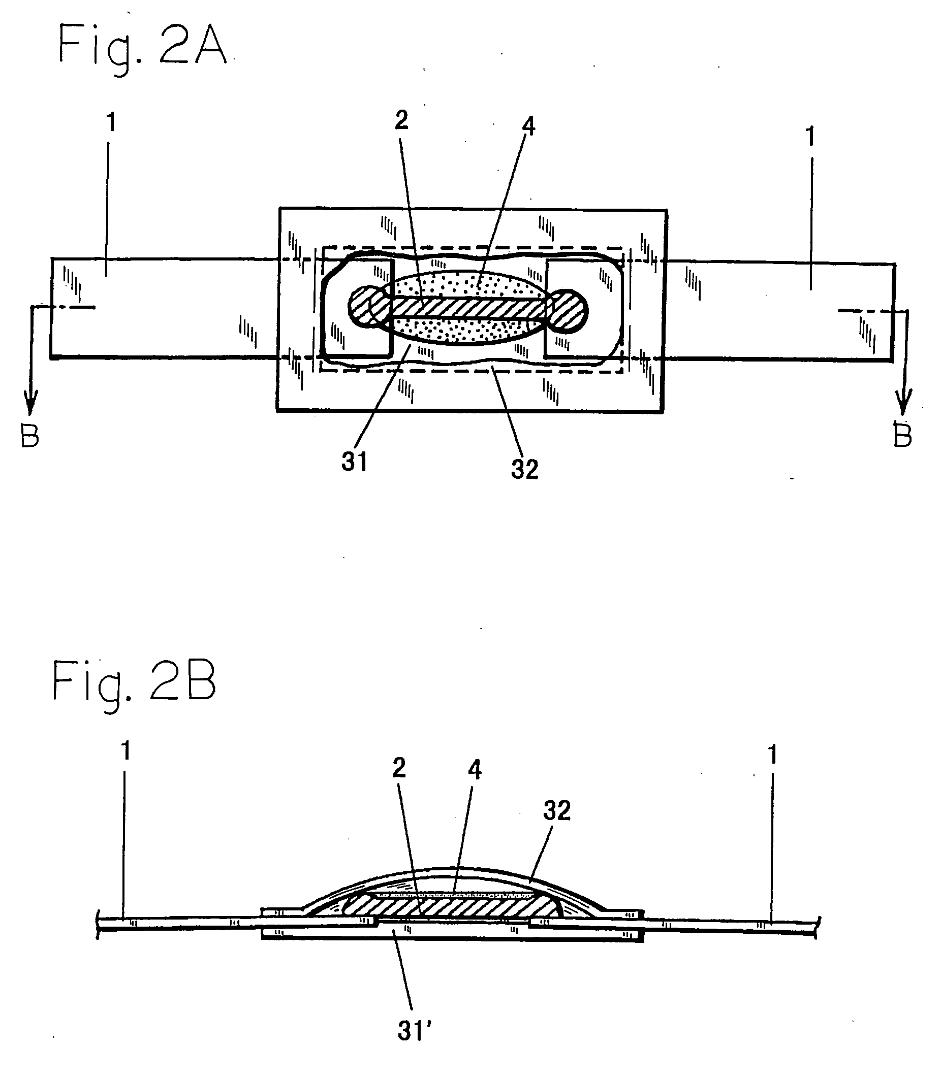
[0070] The fuse of the example is a thermal fuse having a function of a current fuse of the configuration shown in FIG. 1. A film of polyethylene terephtalate having a thickness of 200 .mu.m, a width of 4 mm, and a length of 7.5 mm was used as the resin base film 31 and the resin cover film 32. Copper conductors having a thickness of 150 .mu.m, a width of 3 mm, and a length of 15 mm were used as the flat lead conductors 1. A circular wire having a composition of 52In-48Bi, a sectional area of 0.113 mm.sup.2, and a length of 5 mm was used as the fuse element 2. The distance between the welded portions of the fuse element 2 was set to 3.0 mm. A mixture of a rosin and wax was used as the flux. The thickness of the body portion was 1.2 mm, the resistance was 15.7 m.OMEGA., and the nominal operating temperature was 93.degree. C.


PUM

PropertyMeasurementUnit
Lengthaaaaaaaaaa
Fractionaaaaaaaaaa
Timeaaaaaaaaaa

Abstract

A thin thermal fuse is provided with a rush current resistance performance so as to be usable also as a current fuse. In a thermal fuse in which a low-melting fusible alloy piece 2 having an alloy composition containing 40 to 70% Bi is connected between a pair of flat lead conductors 1, 1, a flux 4 is applied to the low-melting fusible alloy piece 2, and the piece is sandwiched between a resin base film 31 and a resin cover film 32 to provide insulation, the resistance of the low-melting fusible alloy piece 2 is set so as to enable the low-melting fusible alloy piece 2 to be fused off also by Joule heat due to an allowable maximum current of a secondary battery.

Description

[0001] 1. Field of the Invention[0002] The present invention relates to a thin thermal fuse having a function of a current fuse.[0003] In a secondary battery which is useful as a power source for a portable apparatus such as a notebook computer or a portable telephone, particularly, a lithium-ion secondary battery or a lithium polymer secondary battery, the heating temperature in an abnormal state is high because of its high energy density. Therefore, a battery circuit must be interrupted at an allowable maximum temperature of 85 to 95.degree. C. so as to prevent an accident such as explosion from occurring in the battery.[0004] 2. Description of the Prior Art[0005] Such a protector is requested to be thin in order to realize mounting into a battery pack. Therefore, a thin thermal fuse such as shown in FIG. 4 or 5 is used in a protector.[0006] In FIG. 4, 31' denotes a resin base film, and 1', 1' denote flat lead conductors in each of which a front end portion is secured to the rear ...

Claims


Application Information

Patent Timeline
IPC IPC(8): H01H37/76H01H85/02C22C28/00H01H85/04H01H85/06
CPCH01H37/76H01H85/06H01H2037/768A01G31/06A01G33/00C02F3/32
Inventor KAWANISHI, TOSHIRO
Owner UCHIHASHI ESTEC
Why Eureka
Try Eureka