Multi-wavelength laser device

Active Publication Date: 2004-10-07
SHARP FUKUYAMA LASER CO LTD
View PDF5 Cites 240 Cited by
  • Summary
  • Abstract
  • Description
  • Claims
  • Application Information

AI Technical Summary

Problems solved by technology

There are differences between recording and reproducing standards on the CD, CD-R/RW and DVD, and it is impossible for only one type of an LD to cover such different standards.
However, installing as many as three pickups in a recording and reproducing device inevitably increases the size of the recording and reproducing device and also causes increase in costs.
On the other hand, it has not been considered how to arrange three or more LDs having emission wavelengths different from each other when they are integrated together.
This, however, does not bring about the advantage of integrating a plurality of LDs in one pickup.
In the laser device with a plurality of LD

Method used


Image

  • Multi-wavelength laser device
  • Multi-wavelength laser device
  • Multi-wavelength laser device

Examples


embodiment 1

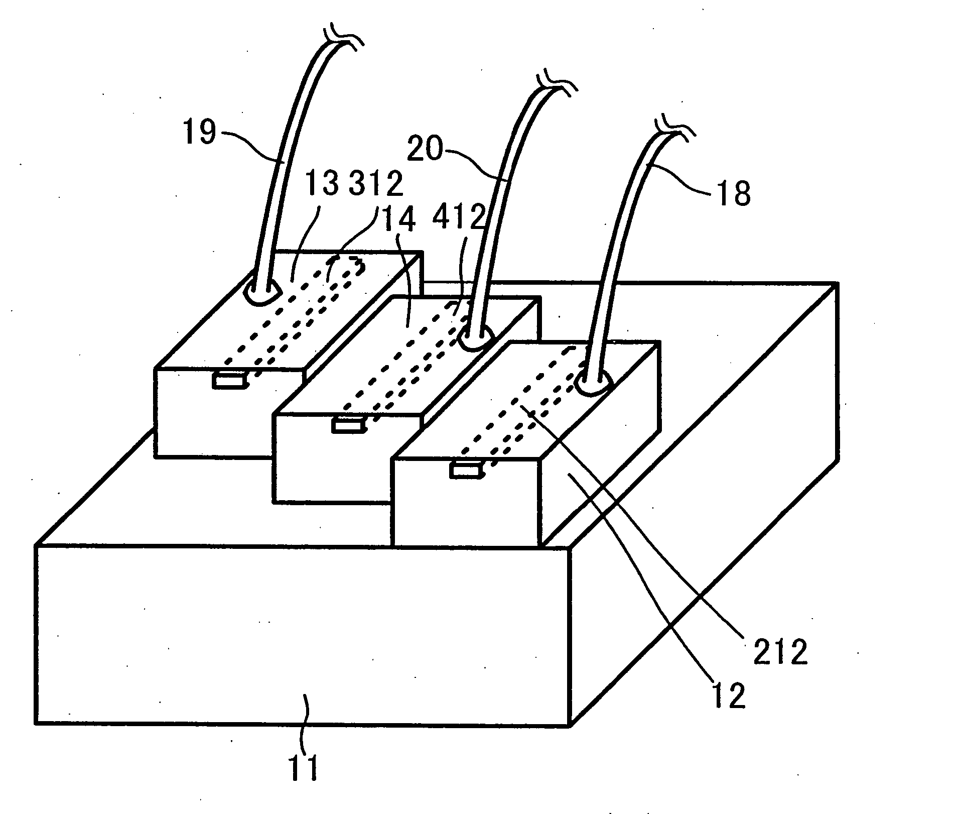
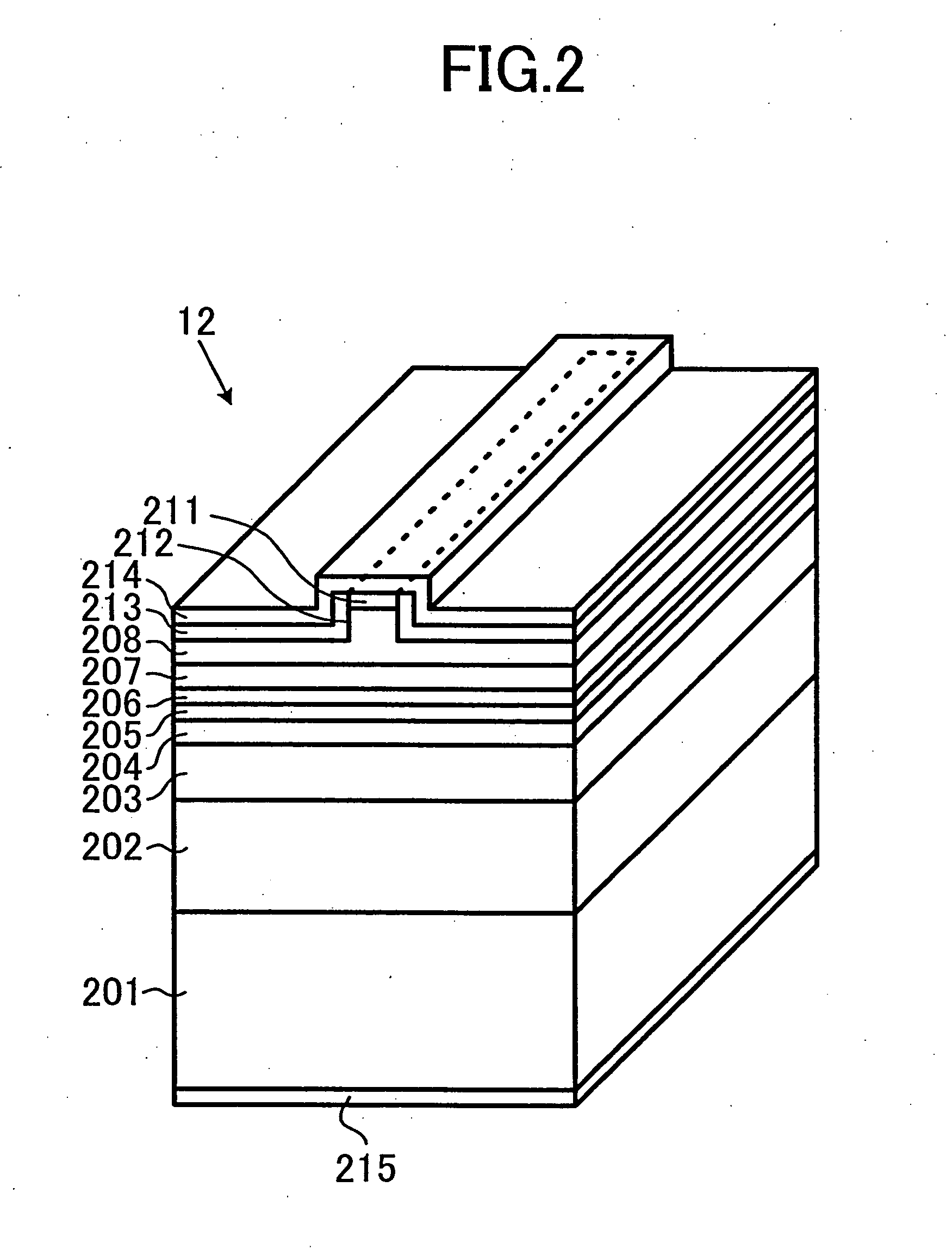
[0038] FIG. 1 is a perspective view schematically illustrating a front portion of a header of a multi-wavelength laser device in embodiment 1 of the present invention. At the front portion of the header, a blue LD 12, an infrared LD 13 and a red LD 14 are disposed on a main surface of a support base 11. These LDs have respective ridge stripes 212, 312 and 412, each including a stripe-shaped waveguide. A first wire 18, a second wire 19 and a third wire 20 are connected to LDs 12, 13 and 14, respectively, for supplying power so that they can operate independently.

[0039] Support base 11 is made of metal including copper as a main component and serves as a heat sink. The LDs on support base 11 are mounted such that laser beams emitted therefrom are approximately parallel to each other. Each LD is mounted with its n-electrode facing on support base 11, i.e., with its p-side up and has the wire connected on the p-electrode side. These wires are connected to locations away from just above ...

embodiment 2

[0055] FIG. 7 is a perspective view schematically illustrating a front portion of a stem of a multi-wavelength laser device in embodiment 2. In embodiment 2 of FIG. 7, the same or corresponding parts as in embodiment 1 are denoted with the same reference numbers and the detailed description thereof will not be repeated.

[0056] Although embodiment 2 is similar to embodiment 1, a characterized feature thereof is that each LD is mounted with its p-side down on support base 11. Such a configuration is advantageous in that distance (height) from support base 11 to the emission point position can easily be controlled. On the other hand, as the emission point position is closer to support base 11 with the p-side down, it is more likely that a part of radiated laser light is interrupted by support base 11. Therefore, support base 11 is provided with a cut 21 in order to prevent laser light from being interrupted by support base 11. Cut 21 will be described below.

[0057] As shown in FIG. 8, gi...

embodiment 3

[0062] FIG. 9 is a perspective view schematically illustrating a front portion of a stem of a multi-wavelength laser device in embodiment 3. In embodiment 3 of FIG. 9 also, the same or corresponding parts as in embodiment 1 are denoted with the same reference numbers and the detailed description thereof will not be repeated.

[0063] A characterized feature of embodiment 3 is that an LD 31 mounted on support base 11 is a monolithic type that can emit light beams of different wavelengths on the same substrate. Specifically, in LD 31, a blue laser portion 32, an infrared laser portion 33 and a red laser portion 34 are formed on the same substrate by crystal growth. Laser portions 32, 33 and 34 respectively include corresponding stripe-shaped waveguides 212, 312 and 412 and can be supplied with power independently. Furthermore, each of mirror facets 220, 320 and 420 of the laser portions is an etched mirror, and LD 31 is formed by division along a dividing line 50 in the direction normal ...


PUM


Abstract

A multi-wavelength laser device includes at least two of a blue laser diode, a red laser diode, and an infrared laser diode, which are arranged in the same direction on the same base. One laser light emission point is arranged behind another in increasing order of wavelengths of the laser diodes.

Description

[0001] This nonprovisional application is based on Japanese Patent Application No. 2003-097954 filed with the Japan-Patent Office on Apr. 1, 2003, the entire contents of which are hereby incorporated by reference.[0002] 1. Field of the Invention[0003] The present invention relates to an optical pickup device compatible with plural kinds of optical disks, and more particularly to a multi-wavelength laser device capable of emitting laser beams with a plurality of wavelengths.[0004] 2. Description of the Background Art[0005] In recent years, it has been actively tried to develop record media with increased record density and also recording and reproducing devices therefor. Digital versatile disks (DVD), for example, are being widely used in a variety of fields as record media for images and are expected to be in increased demand in the future. Therefore, there is a growing demand for developing an optical pickup compatible with a conventional compact disk (CD), a recordable and reprodu...

Claims


Application Information

Patent Timeline
IPC IPC(8): G11B7/125H01L21/52H01S3/10H01S5/02H01S5/022H01S5/026H01S5/223H01S5/323H01S5/343H01S5/40
CPCB82Y20/00H01S5/02212H01L2924/3025H01S5/02252H01S5/02272H01S5/2231H01S5/3432H01S5/34326H01S5/34333H01S5/4031H01S5/4087H01S2304/04H01L2224/48463H01L2924/00H01S5/02326H01S5/0237
Inventor KAWAKAMI, TOSHIYUKITANEYA, MOTOTAKA
Owner SHARP FUKUYAMA LASER CO LTD
Why Eureka
Try Eureka