Laser projection imaging system

A laser projection and imaging system technology, applied in the field of optical engines, to achieve the effect of simplifying the structure, eliminating the need to replace bulbs, and perfect picture quality

Inactive Publication Date: 2009-12-09
SHENZHEN KECHUANG DIGITAL DISPLAY TECH
View PDF0 Cites 16 Cited by
  • Summary
  • Abstract
  • Description
  • Claims
  • Application Information

AI Technical Summary

Problems solved by technology

[0003] The object of the present invention is to provide a laser projection imaging system, which uses laser as the light source of the projection imaging system, has the characteristics of wide color gamut, long life, simple structure, etc., and adopts a rotating optical wedge to effectively solve the problems caused by interference. image problem

Method used


Image

  • Laser projection imaging system
  • Laser projection imaging system
  • Laser projection imaging system

Examples


Embodiment Construction

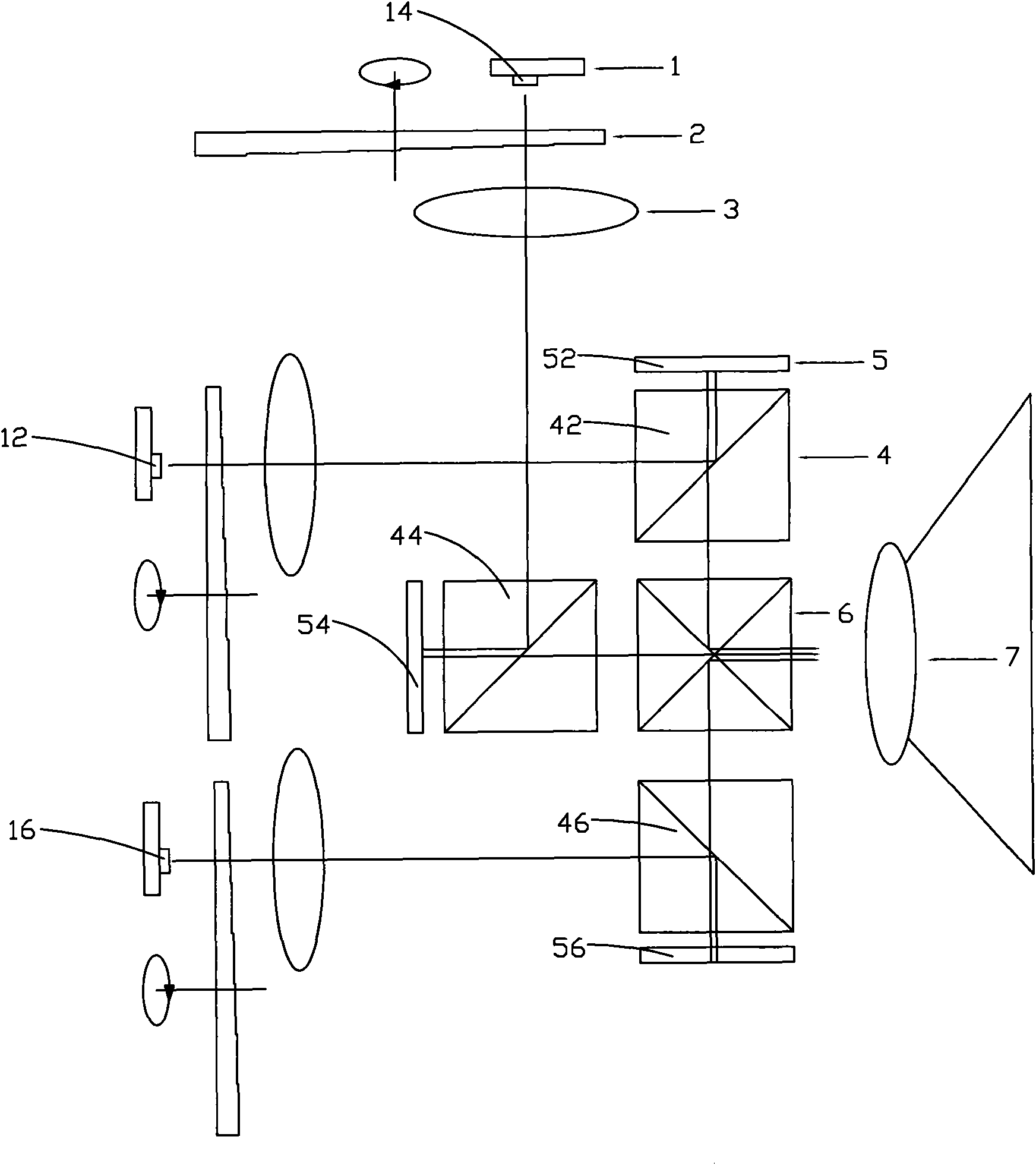
[0018] Such as figure 2 As shown, the laser projection imaging system of the present invention includes: three laser light sources 1 for generating red, green and blue laser light, a projection system 7 for projecting the laser light onto the surface of an object, and a projection system 7 arranged in the propagation path of the laser light. Three rotatable wedges 2 arranged correspondingly to the three laser light sources 1, a homogeneous illumination system 3, three PBS prisms (polarization beam splitter prisms) 4, three imaging devices 5 arranged correspondingly to the three PBS prisms, and A light-combining prism 6 is arranged between the three PBS prisms 4 .

[0019] Wherein, the three laser light sources are three monochromatic lasers that generate red laser, green-blue laser and blue laser respectively, that is, red laser 12 , green laser 14 and blue laser 16 .

[0020] The red laser light source, the green laser light source, and the blue laser light source are respe...


PUM


Abstract

The invention relates to a laser projection imaging system comprising three laser sources, a projection system, three rotatable laser wedges, a uniform laser illuminating system, three PBS prisms, three imaging devices and a laser combining prism, wherein the three laser sources are used for generating a red laser, a green laser and a blue laser; the projection system is used for projecting the lasers on an object surface, the three rotatable laser wedges corresponding to the three laser sources are arranged in a laser propagation path; the three imaging devices respectively correspond to the three PBS prisms; the laser combining prism is arranged among the three PBS prisms; and the red laser, the green laser and the blue laser which are all transmitted by the three laser sources respectively pass through the corresponding laser wedges and the uniform laser illuminating system, are reflected to the three imaging devices through the PBS prisms, pass through the PBS prisms after being reflected from the imaging devices, are transmitted to the projection system through the combination of the laser combining prism and are projected by the projection system. The laser projection imaging system uses the lasers as the projection display laser sources, has wide color range, simple structure, and the like and effectively solves an image spot problem generated by laser interference by adopting the rotatable laser wedges.

Description

technical field [0001] The invention relates to an LCOS (Liquid Crystal On Silicon) optical imaging system using a laser as a light source, in particular to an optical engine of a rear projection TV. Background technique [0002] Currently used projectors usually use UHP (Ultra High Performance) lamps as light sources. refer to figure 1 , this system includes lamp source 100, ultraviolet and infrared filter 110, polarization conversion system 120, uniform light illumination system 3, PBS prism 4 ((polarization beam splitter prism), imaging device 5, light combining prism 6, and projection system 7. In this system, it is necessary to use multiple beam splitters 130 or reflectors 140 to separate the red, green and blue light to irradiate the red, green and blue imaging devices respectively, and the spectrum of the UHP lamp needs to use various filters and polarization conversion systems Adjust to achieve the ideal color coordinates and color gamut. In addition, the use of UH...

Claims


Application Information

Patent Timeline
Patent Type & Authority Applications(China)
IPC IPC(8): G02B27/48G02B27/10G03B21/20H04N9/31
Inventor 李方红汤波
Owner SHENZHEN KECHUANG DIGITAL DISPLAY TECH
Why Eureka
Try Eureka