Logic circuit
a logic circuit and circuit technology, applied in logic circuits, non-denominational number representation computation, pulse counters, etc., can solve the problems of large silicon area and transistors no longer able to conduct signals
- Summary
- Abstract
- Description
- Claims
- Application Information
AI Technical Summary
Benefits of technology
Problems solved by technology
Method used
Image
Examples
first embodiment
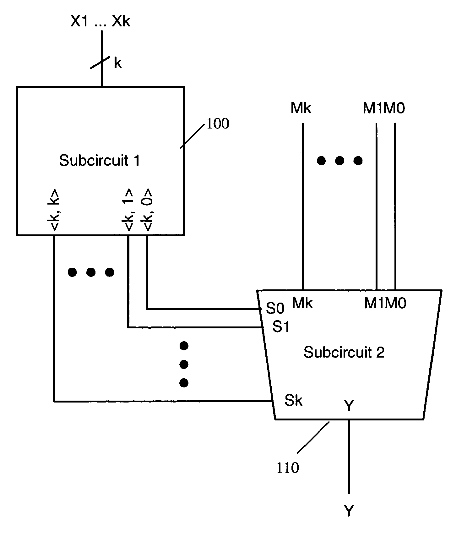
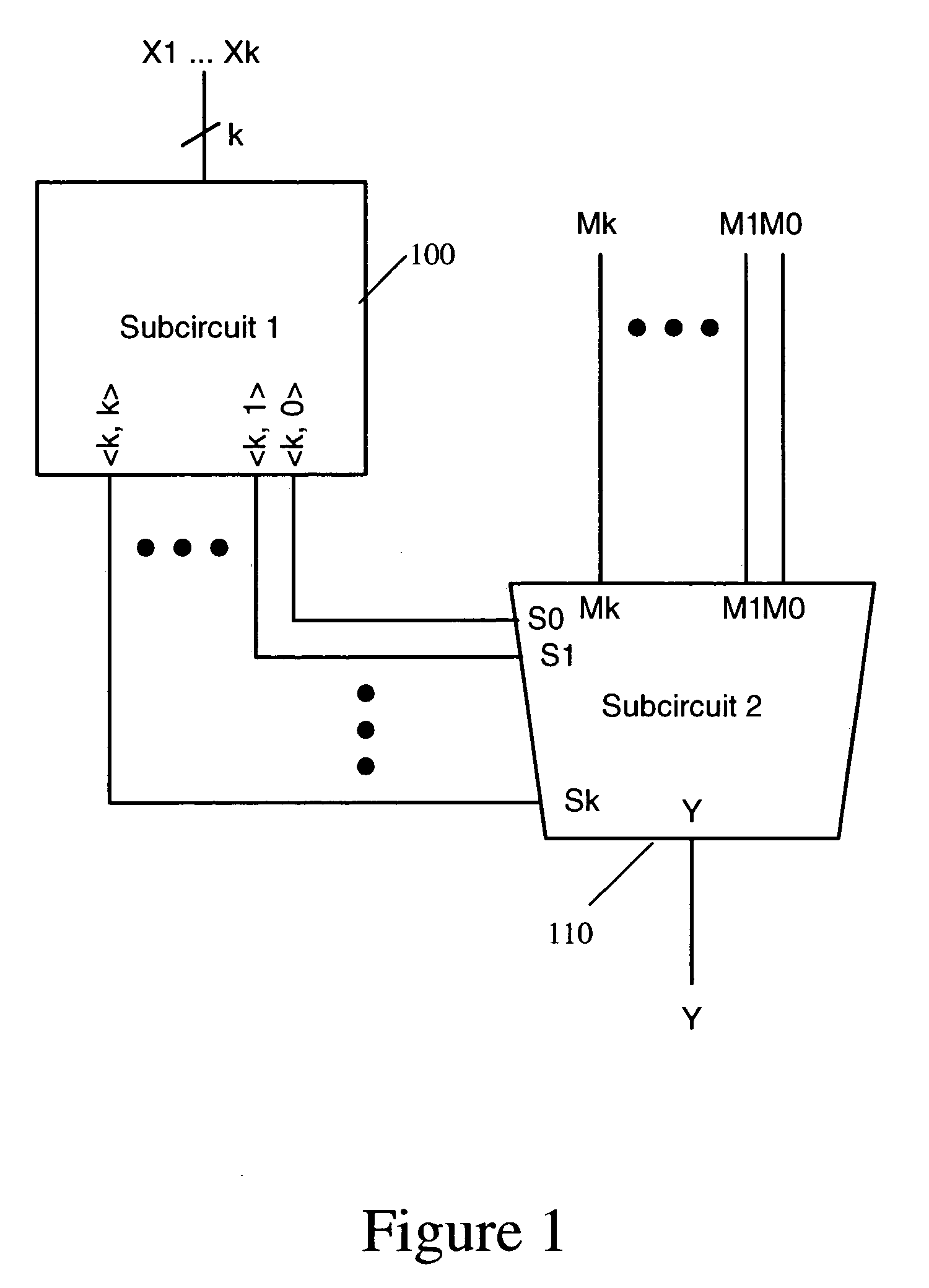
[0037] FIG. 1 is a block diagram of a circuit according to the invention.
[0038] The circuit selects one of a plurality of binary inputs M0, . . . ,Mk, depending on the number of highs amongst a further plurality of binary inputs X1, . . . ,Xk. The circuit has two subcircuits: a first subcircuit 100 and a second subcircuit 110.
[0039] The first subcircuit 100 determines the number of highs amongst the further plurality of binary inputs, X.sub.1, . . . X.sub.k. There are a total of k binary inputs X.sub.1, . . . ,X.sub.k to subcircuit 100. Subcircuit 100 generates k+1 outputs, consisting of a series of selection functions , where j is an integer between 0 and k. Each selection function outputs a high value if there are exactly j high inputs amongst the k inputs to subcircuit 100, and outputs a low value if there are less than or greater than j high inputs amongst the k inputs to subcircuit 100. Each of the selection functions from j=0 to j=k is generated as a separate output signal, gi...
PUM
 Abstract
Description
Claims
Application Information
 - R&D
- Intellectual Property
- Life Sciences
- Materials
- Tech Scout
- Unparalleled Data Quality
- Higher Quality Content
- 60% Fewer Hallucinations
Browse by: Latest US Patents, China's latest patents, Technical Efficacy Thesaurus, Application Domain, Technology Topic, Popular Technical Reports.
© 2025 PatSnap. All rights reserved.Legal|Privacy policy|Modern Slavery Act Transparency Statement|Sitemap|About US| Contact US: help@patsnap.com


