Calculation system of fault coverage and calculation method of the same

a technology of fault coverage and calculation method, which is applied in the direction of error detection/correction, program control, instruments, etc., can solve the problems of not being formed properly, model cannot discern the detection of such open defects, and the fault coverage according to the rate of simply detected faults among the number of assumed faults has a serious problem

Inactive Publication Date: 2004-10-14
KK TOSHIBA
View PDF8 Cites 40 Cited by
  • Summary
  • Abstract
  • Description
  • Claims
  • Application Information

AI Technical Summary

Problems solved by technology

However, this fault model treats a fault on a connection wire extending across a wide range inside the LSI and a fault on a wire extending across a narrow range inside the LSI equally as one fault.
Nevertheless, incidences of defects which cause faults are various and strongly dependent on such layout elements in actual devices, and the traditional fault coverage has not corresponded to such a fact.
Accordingly, the fault coverage according to the rate of the number of simply detected faults from among the number of the assumed faults has a serious problem.
However, as the process design rules become finer, there are more faults of open defects in which minimum-sized vias (contacts for connecting sets of metal wires which are vertically adjacent to each other) are not formed properly, for example.
Here, the net stuck-at fault model has a problem in that the model cannot discern detection of such open defects.
In other words, since only two stuck-at faults are defined with respect to each net in the case of the net stuck-at fault model, the model cannot detect which part of a signal path in the net is activated and detected when a fault has been detected.
Accordingly, there is a risk that a defect in a minimum-sized via (hereinafter referred to as a minimum via) on the path which is not actually activated may remain undetected.
Therefore, in the recently popularized pin stuck-at fault model, it is difficult to determine accurately how large a layout region has been tested in the bidirectional signal wire by an applied test pattern, unless a path from an output to an input is correctly specified.
However, the evaluation equipment cannot correctly specify the path from the output to the input.
Meanwhile, frequency of open defect occurrence may particularly deteriorate greatly in the double vias, then it is also necessary to multiply the number of double vias by a suitable ratio based on the number of minimum vias.
On the contrary, in a bidirectional connection wire adopting a configuration such that output terminals of a plurality of basic cells are connected to input terminals of a plurality of basic cells (a type similar to the bidirectional connection wire adopting the configuration such that output terminals of a plurality of basic cells are connected to input terminals of a plurality of basic cells), a combination of traditional methods cannot clearly determine path which transmits a detected fault.
As a result, such a combination cannot add proper layout weight.
However, when a limitation is provided, a scheme such as prevention of duplicate counting of the same path is necessary.

Method used


Image

  • Calculation system of fault coverage and calculation method of the same
  • Calculation system of fault coverage and calculation method of the same
  • Calculation system of fault coverage and calculation method of the same

Examples


first embodiment

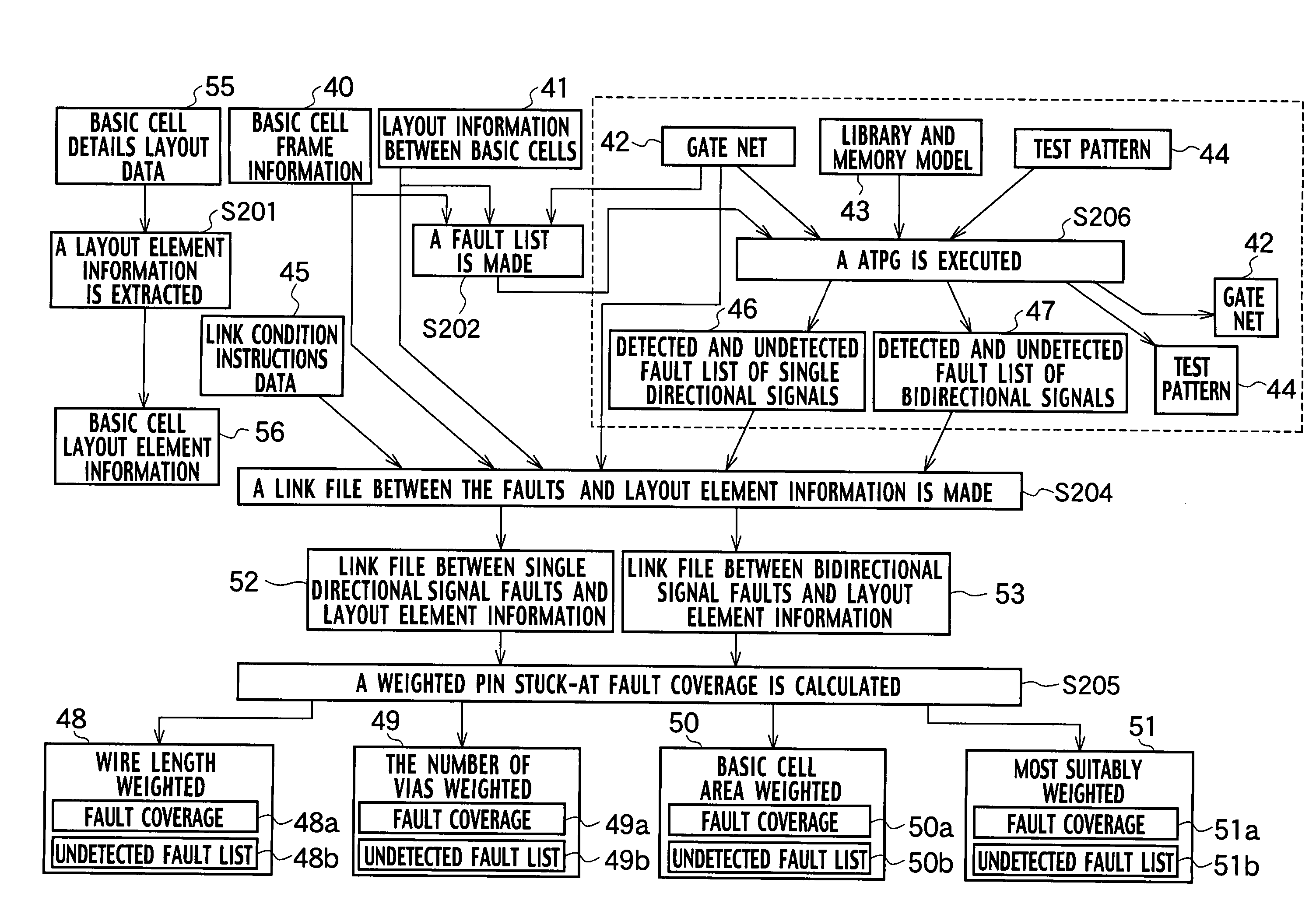
[0066] FIG. 9 is a flowchart showing an example of a method in the case of calculating the fault coverage by use of the fault simulation. FIG. 10 is a flowchart showing an example of a method in the case of calculating fault coverage by use of the ATPG. In the following, examples of the calculation method of fault coverage in accordance with the methods of FIGS. 9 and 10 using the calculation system of fault coverage according to the present invention will be described with reference to FIGS. 11 and 12.

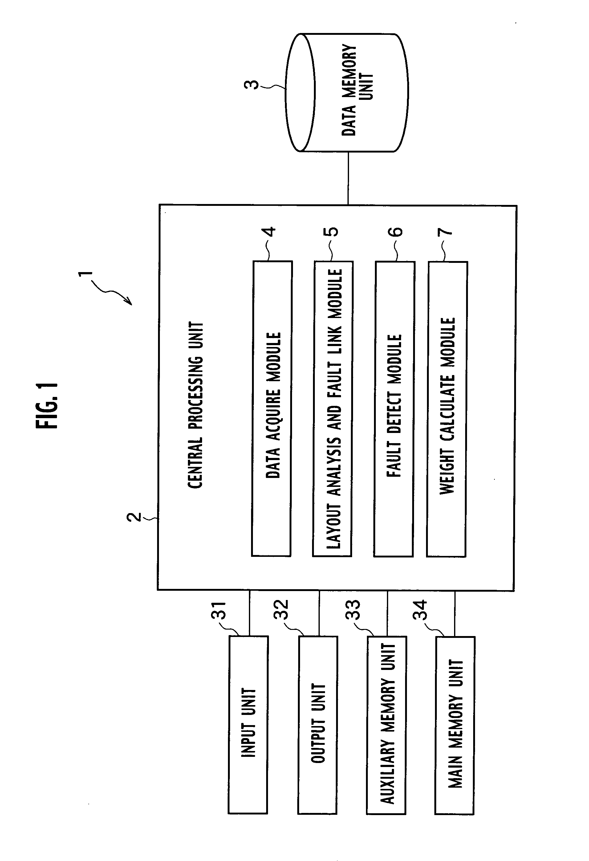
[0067] (a) Firstly, in order to distinguish whether a fault is that concerning a single directional signal or that concerning a bidirectional signal before executing the fault simulation, in Step S121 of FIG. 11, the fault lists are generated for both the single directional signals and the bidirectional signals by use of the layout information between basic cells 41, the basic cell frame information 40, and the gate net 42 which have been stored in the data memory unit 3 of FIG. 3. He...

second embodiment

[0074] Second Embodiment

[0075] In the finer processes in the future, the number of wiring and the wire length between basic cells will be considerably increased along with an increase in the scale of an LSI, and the number of metal wire layers will be 10 layers or more. Since the importance of extraction of the layout elements between the basic cells will be increased, the first embodiment of the present invention did not mention defects, which may occur inside the basic cells, particularly. Meanwhile, there is also a possibility of an increase in faults at an element level such as short circuits between sources and drains of transistors. Such faults can be detected by the net stuck-at fault model. However, considering that a long CPU time is generally required for the fault simulation and the ATPG, it is not reasonable to execute two types (the net and the pin) of stuck-at fault models. Therefore, description will be given of a calculation system of fault coverage and a calculation...


PUM


Abstract

A calculation system of fault coverage includes a data acquiring module acquiring layout information and gate net data, a layout analysis and fault link module extracting a layout element information and generating a undetected fault list, a fault detecting module generating a detected and undetected fault list, and a weight calculating module adding layout element information as weight, based on a link file between faults and layout element information to be generated based on the layout information, the gate net data, and the detected and undetected fault list.

Description

[0001] This application is based upon and claims the benefit of priority from the prior Japanese Patent Applications No. P2003-8785, filed on Jan. 16, 2003; the entire contents of which are incorporated herein by reference.[0002] 1. Field of the Invention[0003] The present invention relates to a calculation system of fault coverage and a calculation method of fault coverage for large scale integrated circuit (LSI), particularly for system LSI or system on chip (SOC).[0004] 2. Description of the Related Art[0005] In order to evaluate quality of an LSI test, a fault model has been assumed corresponding to a logical configuration inside an LSI, then a rate of fault detection has been calculated by simulation using a test pattern produced for the LSI test, and then the quality of the test pattern has been evaluated (estimated). A typical fault model includes a "net stuck-at fault model" which assumes that one of connection wiring between basic cells inside the LSI is fixed to either pow...

Claims


Application Information

Patent Timeline
Patent Type & Authority Applications(United States)
IPC IPC(8): G01R31/28G06F11/26G06F17/50G06F11/263
CPCG06F11/261G06F11/263
Inventor NOZUYAMA, YASUYUKI
Owner KK TOSHIBA
Why Eureka
Try Eureka