
High spatial resoulution imaging and modification of structures

a high-spatial resoulution and structure technology, applied in the direction of optical radiation measurement, spectrophotometry/monochromator, spectrometry/spectrophotometry/monochromator, etc., can solve the problems of inability to easily focus light with a wave length of 250 nm, inefficient optics, and high cost of application of known methods, so as to improve the resolution and speed up the procedure , the effect of simple phase shi

Active Publication Date: 2004-10-28
MAX PLANCK GESELLSCHAFT ZUR FOERDERUNG DER WISSENSCHAFTEN EV
View PDF7 Cites 87 Cited by
  • Summary
  • Abstract
  • Description
  • Claims
  • Application Information

AI Technical Summary

Benefits of technology

The present invention is a new method for imaging samples using a substance with two different optical states. The substance can switch between the two states using a switch over signal. The method has several advantages over existing fluorescence microscopy methods. Firstly, the optical properties of the substance in the two states are different, allowing for easier identification of the measurement or writing signal. Secondly, the switch over process is reversible, meaning the substance can return to its original state without needing a new switch over signal. Thirdly, the method uses a small number of optical signals, minimizing the impact on the sample. Fourthly, the method can be used with different types of optical signals, such as electric or thermal signals. Fifthly, the method can be used with different types of samples, such as molecules or molecule groups. Finally, the method can be used with existing fluorescence microscopes without needing significant additional efforts.

Problems solved by technology

Although this method of fluorescence microscopy obviously provides a spatial resolution below the diffraction limit it also has disadvantages.
Thus, as a rule, a pulsed high power laser is necessary for the stimulation light beam, which makes the application of the known method quite cost-intensive.
These disadvantages also apply to known GSD methods as time limitations and power requirements are here also set by short life times of the involved energy states.
The problem here is, that light with a wave lengths<250 nm is not easily focused, and the optics to be used become expensive and inefficient.

Method used


Image

  • High spatial resoulution imaging and modification of structures
  • High spatial resoulution imaging and modification of structures

Examples


Embodiment Construction

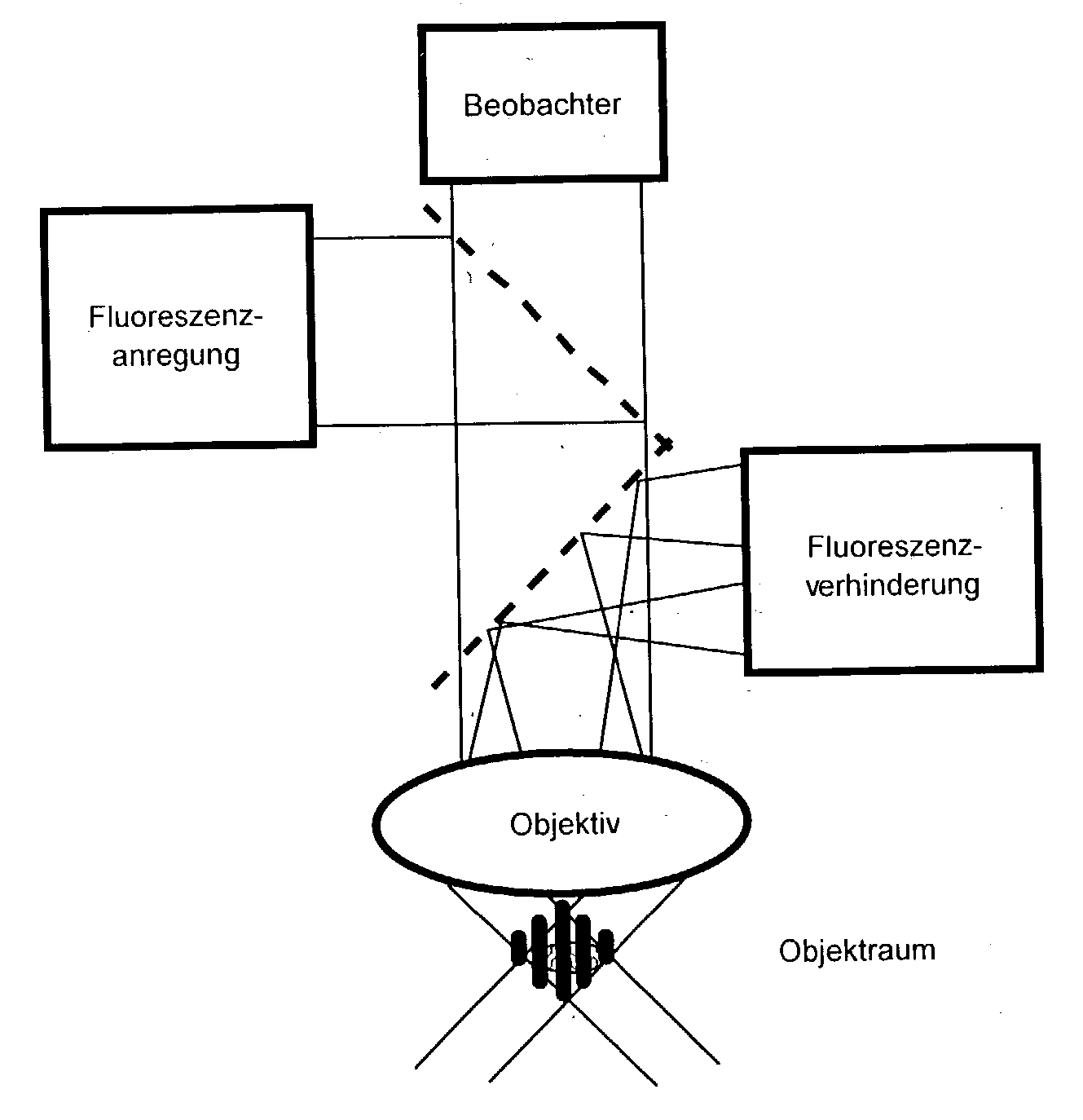
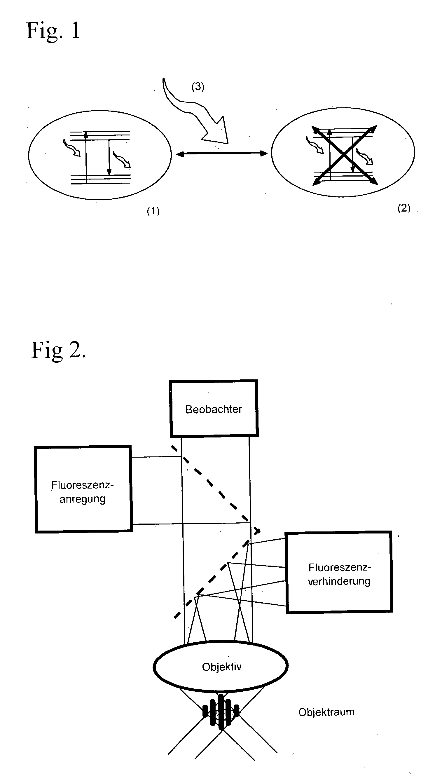
[0015] Using substances having two states with different optical properties is a common feature of all aspects of the invention. Further, the substance can purposefully be switched with a switch over signal from the first to the second state. This process is reversible. I.e. the substance can also be returned to the first state. The optical properties of the substance in the first state differ from those in the second state in that only they support the measurement signal or the writing signal, respectively. However, it is not necessary that the relevant optical properties are "binary", i.e. it is not necessary that they are present in the one state at 100% and in the other state at 0%. Instead, it is sufficient, if the relevant optical properties show such big differences that at least an essential association of the measurement signal or the writing signal, respectively, to the first state is possible. These states can be two different conformational states of a molecule or a mole...


PUM

PropertyMeasurementUnit
life timeaaaaaaaaaa
resolution imagingaaaaaaaaaa
optical measurementaaaaaaaaaa

Abstract

In a method of high spatial resolution imaging or modifying a structure, the structure is marked with a substance which is selected from the group of substances which can be transferred from a first state having first optical properties to a second state having second optical properties by means of an optical switch over signal. Then, the second state of the substance is adjusted with the switch over signal except for a spatially limited area. If the substance and the switch over signal are adapted to each other in such a way, that everywhere where the switch over signal exceeds a threshold value essentially the second state of the substance is adjusted, and if the spatial area purposefully omitted by the switch over signal is an intensity minimum of an interference pattern, the spatial area of the structure in which the substance is within the first state becomes smaller than the diffraction limit for the switch over signal.

Description

[0001] This invention relates to a method of high spatial resolution imaging a structure of a sample, comprising a substance having at least two different states, especially of a biologic sample, the method comprising the steps of changing the state of the substance with an optical switch over signal which purposefully omits at least one spatial area, and registering an optical measurement signal from at least one of the spatial areas purposefully omitted by the switch signal.[0002] Further, the invention relates to a method of high spatial resolution modification of an optical structure, especially the content of an optical data storage or the photosensitive layer of a substrate which is to be changed microlithographically, the method comprising the steps of providing a structure consisting of the substance having special optical properties and changing an optical state of the substance in a spatially limited area by means of an optical writing signal. The structure made of the sub...

Claims


Application Information

Patent Timeline
Patent Type & Authority Applications(United States)
IPC IPC(8): G01J3/30G11B7/24G11B7/24044G11B7/246G11B7/2467
CPCG01N21/6428G01N21/6458G02B21/16G02F1/0126G11B7/00455G11B7/24044G11B7/2467G11C13/04G11C13/041
Inventor HELL, STEFAN
Owner MAX PLANCK GESELLSCHAFT ZUR FOERDERUNG DER WISSENSCHAFTEN EV
Learn More