Sigmoid valve and method for its percutaneous implantation

a sigmoid valve and percutaneous implantation technology, applied in the field of one-way valves, can solve the problems of backflow ("regurgitation"), impaired function of the sigmoid valve, and altered circulation of blood and the hear

Inactive Publication Date: 2004-10-28
THE INT HEART INST OF MONTANA FOUND
View PDF11 Cites 426 Cited by
  • Summary
  • Abstract
  • Description
  • Claims
  • Application Information

AI Technical Summary

Problems solved by technology

In disease, the function of the sigmoid valves is impaired either through narrowing of the valve ("stenosis") or lack of complete closure, which results in backflow ("regurgitation").
In both circumstances, the whole circulation of the blood and the heart is altered and causes severe symptoms in the patient.
Although replacement of the diseased cardiac valves is frequently performed with prostheses, replacement of the venous valves is not done because of the lack of an appropriate prosthesis.

Method used


Image

  • Sigmoid valve and method for its percutaneous implantation
  • Sigmoid valve and method for its percutaneous implantation
  • Sigmoid valve and method for its percutaneous implantation

Examples


Embodiment Construction

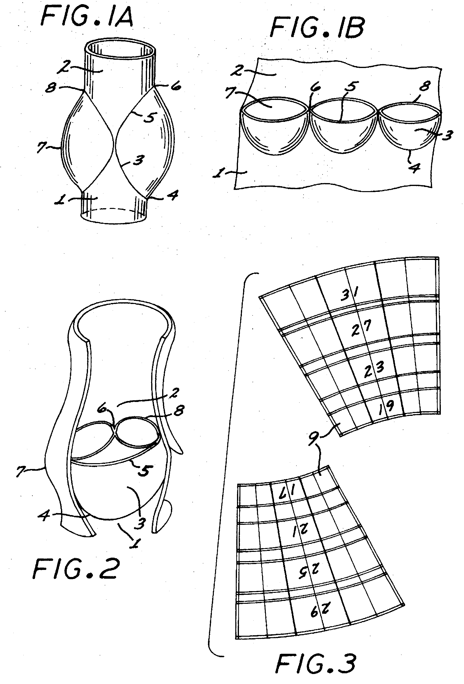
[0060] Referring now to the drawing figures, FIGS. 1A and 1B are sketches of the basic anatomic structure of a sigmoid valve, such as the aortic valve, pulmonary valve, or the valves present in peripheral veins. All of them are substantially a conduit or root with inflow 1 and outflow 2 orifices separated by three leaflets or cusps 3. FIG. 1A represents a longitudinal section of the root, and FIG. 1B represents a root that has been opened longitudinally to show its major components. The leaflets are attached to the valve annulus 4, which is scalloped, as shown in FIG. 1B. The point where the free edges 5 of the leaflets or cusps 3 come in contact are the commissures 6. Opposite each leaflet, the vessel wall has three bulges or Sinuses of Valsalva 7. The distal (or outflow) limit of the sinuses of Valsalva 7 is the sinotubular junction 8.

[0061] These structures are depicted closer to reality in FIG. 2, which represents an aortic valve root through an opened aorta. The anatomic landma...


PUM


Abstract

A multi-leaflet valve adapted to serve as a prosthesis for diseased native valve of a mammal is incorporated in self-expandable or inflatable endovascular stents or stents to form a combination which is introduced on a catheter with a guide wire into the circulatory system of the mammal to replace the diseased native valve. Once the combination is at the desired location the stent is caused to expand and affix itself to the patient's vessel wall. The prosthetic valve has the shape of a truncated cone that has an inflow and an outflow orifice with leaflets forming the outflow orifice and forming a plurality of commissures. A first flexible circular support is affixed in a substantially circular fashion around the truncated cone in proximity of the inflow orifice, and a second flexible circular support is affixed at the location of the commissures to form a circle around the truncated cone in proximity of the outflow orifice. The circular supports maintain the shape of the valve during the surgical implantation procedure and thereafter.

Description

CROSS-REFERENCE TO PRIORITY APPLICATION[0001] The present application claims the priority of provisional application serial No. 60 / 373,171 filed on Apr. 16, 2002.[0002] 1. Field of the Invention[0003] The present invention is in the field of one-way valves designed to replace diseased venous or arterial valves present in the circulatory system. More specifically, the present invention is directed to the replacement of a diseased valve in the circulatory system through a percutaneous approach.[0004] 2. Description of Background Art[0005] The Sigmoid Valves[0006] The mammalian circulation needs the presence of one-way valves to maintain forward blood flow. These valves are found in the outflow of the right and left ventricles ("pulmonary" and "aortic" valves, respectively), and in the large veins. Because of their similar anatomic structure, they are called "sigmoid" or "semilunar" valves. This common structure consists of one, two, or three very thin flaps called "cusps" or "leaflets...

Claims


Application Information

Patent Timeline
Patent Type & Authority Applications(United States)
IPC IPC(8): A61F2/24
CPCA61F2/2412A61F2/2415A61F2/2418A61F2/2433A61F2/2436A61F2/2475A61F2220/0075
Inventor DURAN, CARLOSSANZ, MARK
Owner THE INT HEART INST OF MONTANA FOUND
Why Eureka
Try Eureka