Apparatus for synthesizing laser beams

a laser beam and apparatus technology, applied in the field of apparatus for synthesizing laser beams, can solve the problems of limited power of laser introduced into optical fibers, the number of beams to be synthesized, and the difficulty of producing such a redirection system

Inactive Publication Date: 2004-11-25
ADTEC ENG +1
View PDF15 Cites 37 Cited by
  • Summary
  • Abstract
  • Description
  • Claims
  • Application Information

AI Technical Summary

Problems solved by technology

In the technology, though the beam synthesizing efficiency (the efficiency of synthesizing the beam bundles radiated from a plurality of semiconductor lasers and introduced into a single optical fiber) is as high as 90%, the number of beams to be synthesized is limited since the angle of incidence of the beam bundle to the optical fiber is limited according to the numerical aperture (e.g., NA=0.2) of the optical fiber.
That is, the power of the laser beams to be synthesized and introduced into the optical fiber is limited according to the numerical aperture of the optical fiber.
It is difficult to produce such a redirection system.
Further, since the dimensions of the beam waist are proportional to the wavelength, as the dimensions of the beam waist become smaller with recent shortening the wavelengths of lasers, it becomes necessary that the redirection system is smaller in size and more accurately fixed, which makes it more difficult to produce the redirection system.
The system described above, where the whole beam bundle comprising laser beam bundles radiated from a plurality of semiconductor lasers and offset is converged and passed through a redirection system to align the propagating directions of the bundles with each other, and then the laser beam bundles are converged by a condenser optical system and introduced into the optical fiber to be synthesized into a synthesized bean bundle, is disadvantageous in that the optical path along which each of the beam bundles propagates from the semiconductor laser to the optical fiber is elongated, and at the same time, a number of optical parts including the lens for offsetting the beam bundles and the lens for converging the whole beam bundle must be disposed on the optical path, whereby the size of the apparatus is increased.
Further, the system gives rise to a difficult problem th...

Method used


Image

  • Apparatus for synthesizing laser beams
  • Apparatus for synthesizing laser beams
  • Apparatus for synthesizing laser beams

Examples


first embodiment

[0115] the present invention will be described, hereinbelow.

embodiment 1-1

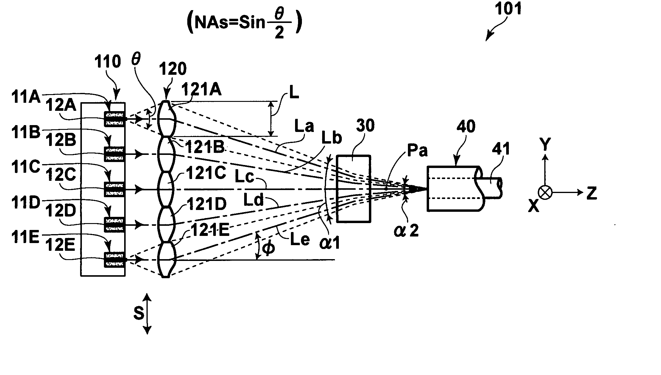
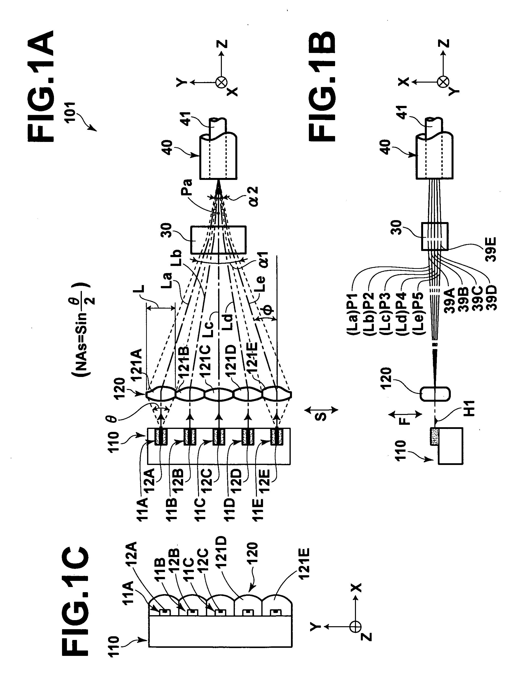
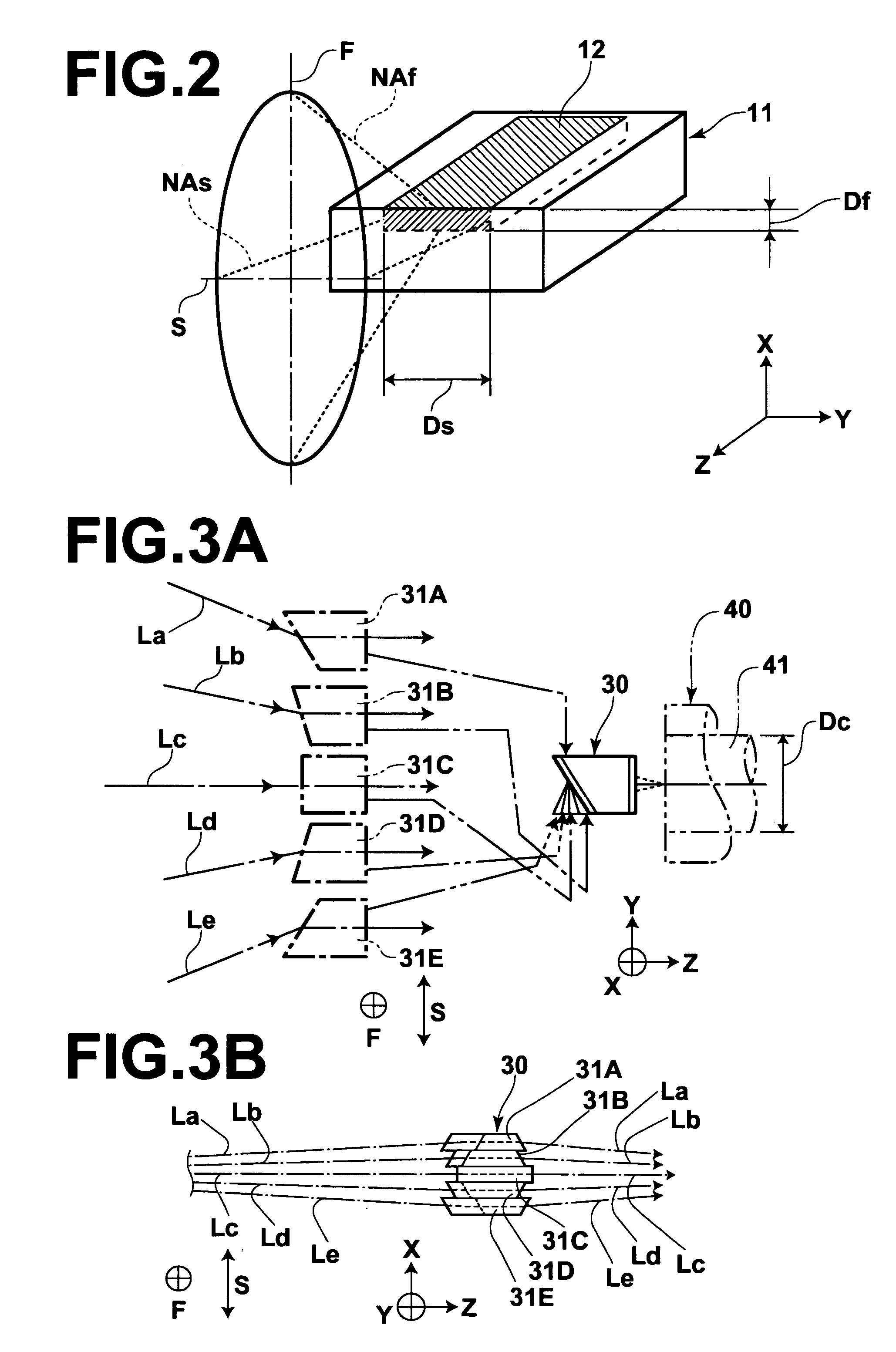
[0116] FIGS. 1A to 1C are views showing a brief arrangement of a laser beam synthesizing apparatus in accordance with an embodiment 1-1 of a first embodiment of the present invention, where FIG. 1A is a plan view showing the laser beam synthesizing apparatus as seen from above, FIG. 1B is a front view showing the laser beam synthesizing apparatus as seen in the direction in which the semiconductor lasers are arranged, and FIG. 1C is a left side view showing the laser beam synthesizing apparatus as seen in the direction of the optical axes of the beam bundles. FIG. 2 is a perspective view showing a manner in which a laser beam bundle is radiated from the active layer of the semiconductor laser, and FIGS. 3A and 3B are views showing a structure of the convergent angle transforming optical system and a state of the beam bundles synthesized in the optical fiber through the convergent angle transforming optical system, where FIG. 3A is a plan view showing the structure of the convergent ...

embodiment 1-2

[0131] A laser beam synthesizing apparatus in accordance with an embodiment 1-2 of a first embodiment of the present invention will be described, hereinbelow. FIGS. 5A to 5C are views showing a brief arrangement of the laser beam synthesizing apparatus, where FIG. 5A is a plan view showing the laser beam synthesizing apparatus as seen from above, FIG. 5B is a plan view showing the laser beam synthesizing apparatus as seen in the direction in which the semiconductor lasers are arranged, and FIG. 5C is a left side view showing the laser beam synthesizing apparatus as seen in the direction of the optical axes of the beam bundles. FIGS. 6A and 6B are views showing a function of offsetting the light bundles of the offset lens element forming the offset lens, where FIG. 6A are schematic views of the lens element with Y-direction directed upward, and FIG. 6B are schematic views of the lens element with X-direction directed upward. FIG. 7 is a view showing a state where the convergent angle...


PUM


Abstract

Laser beams are synthesized by offsetting in different positions in the direction of the fast axis beam bundles radiated from semiconductor lasers, converging the optical axes of the beam bundles in the fast axis view, and introducing the beam bundles into an optical fiber after converging them in the directions of the fast and slow axes. A convergent angle transforming optical system is disposed further upstream of the upstream-most position in the positions where the optical axes of the beam bundles converged in the fast axis view intersect in the fast axis view. The whole beam bundle formed of the beam bundles converged in the fast axis view is passed through the convergent angle transforming optical system so that the angle of convergence of the whole beam bundle or part of the beam bundles is made smaller in the fast axis view, and introduced into the optical fiber.

Description

[0001] 1. Field of the Invention[0002] This invention relates to an apparatus for synthesizing laser beams, and more particularly to an apparatus for synthesizing laser beam bundles respectively radiated from a plurality of semiconductor lasers into a synthesized laser beam bundle and converging the synthesized laser beam bundle into optical fiber.[0003] 2. Description of the Related Art[0004] There has been known a technology in which bundles of laser beams respectively radiated from a plurality of semiconductor lasers arranged in one direction are passed through a collimator lens into parallel beam bundles (having parallel optical axes) arranged in one direction, and the whole parallel beam bundles are condensed and introduced into a single optical fiber, whereby a laser beam of a high energy density is caused to propagate the optical fiber. See, for instance, U.S. Patent Laid-Open No. 20020090172.[0005] In the technology, though the beam synthesizing efficiency (the efficiency of...

Claims


Application Information

Patent Timeline
IPC IPC(8): G02B6/42G02B27/09H01S3/08H01S5/00H01S5/02H01S5/40
CPCG02B27/0961H01S5/005H01S5/02284H01S5/4012H01S5/4031G02B19/0057G02B19/009G02B19/0028G02B19/0014H01S5/02251
Inventor YAMANAKA, FUSAOOKAZAKI, YOJIGOTO, CHIAKISHIMOTSU, SHINICHI
Owner ADTEC ENG
Why Eureka
Try Eureka