
Waterpump

a water pump and water pump technology, applied in the direction of positive displacement liquid engines, piston pumps, liquid fuel engines, etc., can solve the problems of reducing the pump efficiency compared with supplied electricity, reducing the efficiency of the pump, and reducing the quantity of coolant supplied and the pressur

Inactive Publication Date: 2004-11-25
AISAN IND CO LTD
View PDF6 Cites 24 Cited by
  • Summary
  • Abstract
  • Description
  • Claims
  • Application Information

AI Technical Summary

Benefits of technology

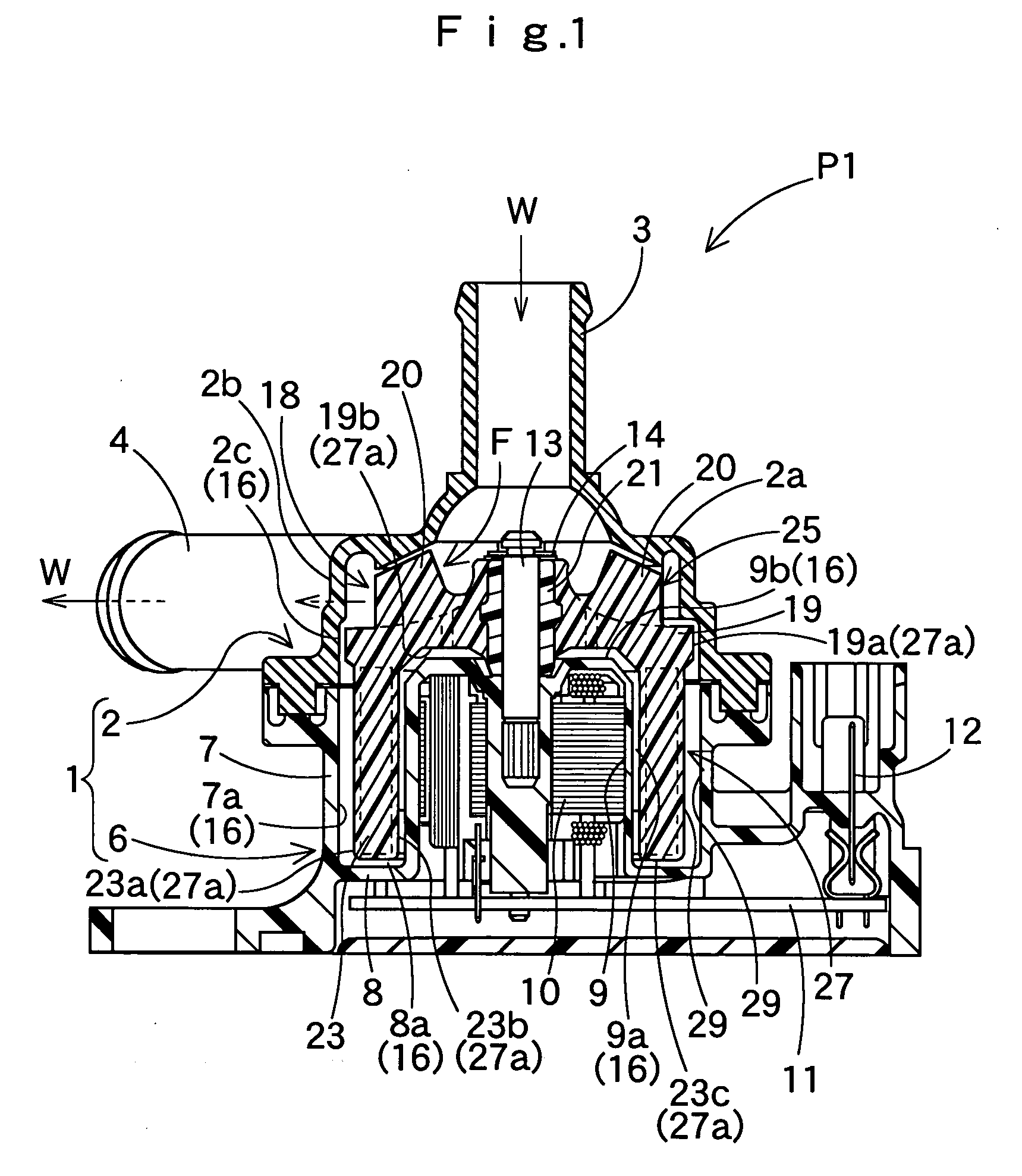
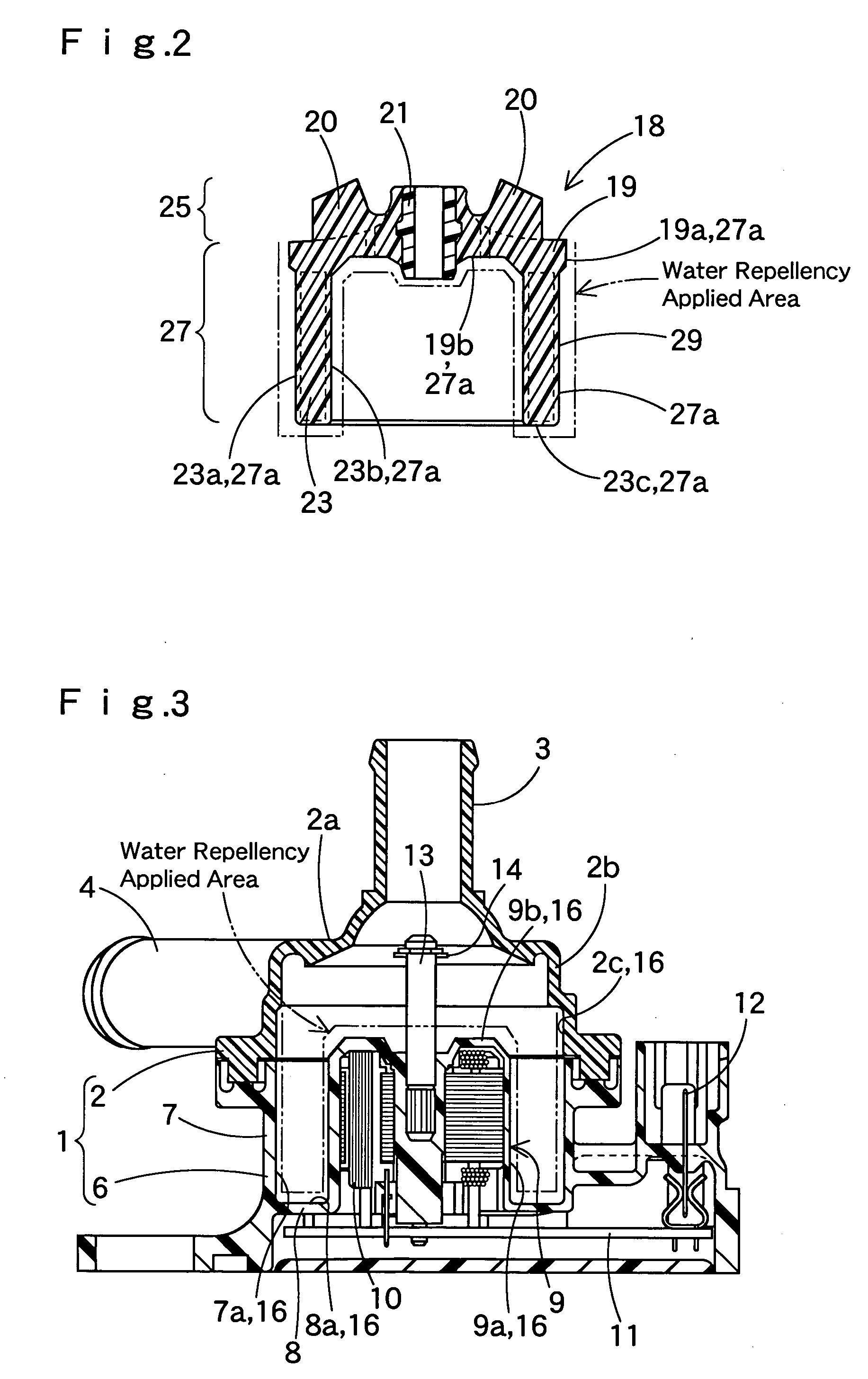
[0011] In the waterpump of the present invention, since at least either one of the outer surface of the non-working section or the plane of the housing confronting the outer surface has water repellency, fluid in the non-working section of the rotor in service reduces shear stress. Consequently, the rotor is able to rotate smoothly with less friction with the fluid.
[0012] Therefore, the waterpump of the present invention is able to improve pump efficiency by reducing shear stress of the fluid in the vicinity of the non-working section, and consequently consumes less electricity.
[0013] Water repellency in this invention refers to a property that enables reduction of shear stress of fluid in the surfaces of the non-working section and the housing in the vicinity of the non-working section. It is sufficient if the surfaces of the non-working section and the housing in the vicinity thereof are enabled to have an enlarged contact angle with fluid or reduced surface energy with fluid. Water repellency can be applied to the surfaces of the non-working section and the housing in the vicinity thereof, for example, by surface treatment such as coating the surf aces of the non-working section and the housing in the vicinity thereof with water repellant like fluorine plastic used for glass coating material by vapor deposition, welding, or dipping, or by plating for forming smooth surface, which is exemplified by electroless nickel plating. Alternatively, water repellency can be applied also by forming the non-working section and the housing from water repellent material such as fluorine plastic, or by mixing water repellent material into the material for forming the non-working section and the housing.
[0015] Especially in the outer-rotor type pump, the magnet section to be the non-working section of the rotor has a greater radius than in an inner-rotor type pump, and thus the surface area of the non-working section is increased. Accordingly, with water repellency of the surfaces of the magnet section and the plane of the housing confronting the magnet section surface, a significant effect of improving pump efficiency is obtained in comparison with a case where no water repellency is applied.

Problems solved by technology

In conventional waterpumps, however, when in service, it is inevitable that shear stress of coolant occurs between an outer surface of the non-working section including the magnet section and a plane of the housing confronting the outer surface of the non-working section with coolant interposed.
In other words, friction between the rotor and coolant is prone to restrain the quantity of coolant supplied and the pressure of the coolant in comparison with electricity supplied to the stator.
Especially in rapid rotation area where the rotor rotates at over 3000 rpm, for example, increase of shear stress of the coolant becomes conspicuous, which lowers the pump efficiency compared with supplied electricity.

Method used


Image

  • Waterpump
  • Waterpump
  • Waterpump

Examples


Embodiment Construction

[0023] Preferred embodiments of the present invention are now described below with reference to the accompanying drawings. However, the invention is not limited to the embodiments disclosed herein. All modifications within the appended claims and equivalents relative thereto are intended to be encompassed in the scope of the claims.

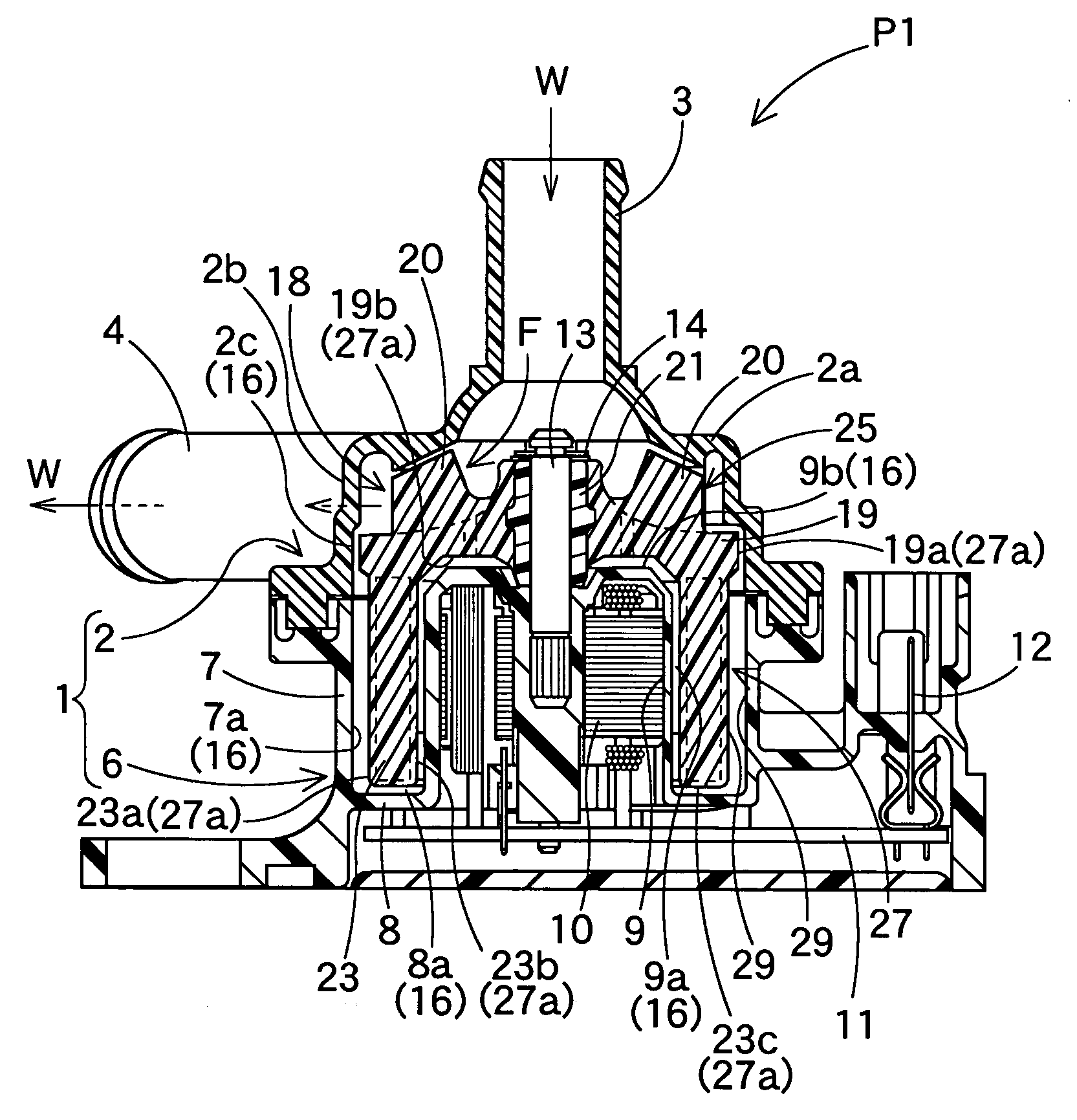
[0024] FIGS. 1 to 3 illustrate a first embodiment P1 of the waterpump according to the present invention. The waterpump P1 is a magnetic coupling pump for pumping engine coolant W for vehicles. The pump P1 includes a housing 1 which is made from synthetic resin and has therein a rotor 18 with a plurality of impellers 20 for feeding the coolant W.

[0025] The housing 1 includes a pump chamber 2 in which the impellers 20 of the rotor 18 are located, and a motor chamber 6 located below the pump chamber 2. The pump chamber 2 has a ceiling wall 2a and has a substantially cylindrical shape as a whole. An inlet pipe 3 for introducing the coolant W is projected upw...


PUM

PropertyMeasurementUnit
shear stressaaaaaaaaaa
magnetic fieldaaaaaaaaaa
pressureaaaaaaaaaa

Abstract

An electrically driven waterpump includes a rotor having impellers for feeding fluid. The rotor is housed in a housing. The rotor includes: a working section located in the fluid and contacting the fluid in a main passage of the fluid stirred by the impellers; and a non-working section located in the fluid and apart from the main passage of the fluid. Water repellency is applied to at least either one of an outer surface of the non-working section or a plane of the housing confronting the outer surface of the non-working section with the fluid interposed, so that shear stress of the fluid is reduced, and pump efficiency is improved.

Description

[0001] The present application claims priority from Japanese Patent Application No. 2003-142386 of Hatano et al., filed on May 20, 2003, the entirety of which is hereby incorporated into the present application by reference.[0002] 1. Field of the Invention[0003] The present invention relates to an electric waterpump for pumping fluids such as engine coolant for vehicles.[0004] 2. Description of the Related Art[0005] In conventional electric waterpumps of this kind such as a magnetic coupling pump for engine coolant for vehicles, a rotor having impellers for feeding coolant is located in a housing, as disclosed in Japanese Laid Open Patent Application No. JP10-311290.[0006] In this waterpump, a magnet section is located in a part of the rotor apart from impellers, while a stator is located around the rotor toward the housing to generate a rotating magnetic field for driving the magnet section when electrified.[0007] The rotor is submerged in coolant, and is constituted by two parts: ...

Claims


Application Information

Patent Timeline
Patent Type & Authority Applications(United States)
IPC IPC(8): F01P5/12F04D13/02F04D13/06F04D29/02F04D29/22F04D29/42
CPCF01P2005/125F04D13/0606F04D29/026F04D29/426F05D2300/437F05D2300/507
Inventor HATANO, MAKOTOFUJII, SHINICHI
Owner AISAN IND CO LTD
Learn More