Method of manufacturing oxide superconducting wire

a superconducting wire and oxide technology, applied in superconductors/hyperconductors, line/current collector details, electrical equipment, etc., can solve the problems of reducing the critical current density, disadvantageously reducing the superconductivity of the obtained oxide superconducting wire, and insufficient inhibition of the superconducting wir

Inactive Publication Date: 2004-12-02
SUMITOMO ELECTRIC IND LTD
View PDF14 Cites 5 Cited by
  • Summary
  • Abstract
  • Description
  • Claims
  • Application Information

AI Technical Summary

Problems solved by technology

However, the wire is blistered in the aforementioned heat treatment step for sintering, to disadvantageously reduce the superconductivity of the obtained oxide superconducting wire.
Thus, voids are formed between oxide superconducting crystals in sintering, to disadvantageously reduce the critical current density.
Further, the oxide superconducting wire cannot be sufficiently inhibited from blistering caused in sintering due to the internal pressure of about 4 atm (0.4 MPa), and hence the critical current density is also disadvantageously reduced.
In the method according to Japanese Patent No. 2592846, it is difficult to control the partial oxygen pressure in the heat treatment due to application of the excessively high pressure of 500 to 2000 kg / cm.sup.2 (about 50 MPa to 200 MPa), to reduce the critical current density.
Thus, the value of the oxygen concentration in the pressurized atmosphere is so remarkably reduced that it is disadvantageously difficult to control the partial oxygen pressure due to strong influence by a measurement error or the like.
When abrupt decompression is thereby caused in the vessel, the pressure in the wire increases as compared with that outside the wire, to blister the wire.
If a heating vessel is abruptly decompressed at this time, the pressure in the wire increases as compared with that outside the wire, to blister the wire.
However, the integumentary thickness of a wire having a small silver ratio cannot be increased due to a small ratio of a metal portion.

Method used


Image

  • Method of manufacturing oxide superconducting wire
  • Method of manufacturing oxide superconducting wire
  • Method of manufacturing oxide superconducting wire

Examples


first embodiment

[0076] First Embodiment

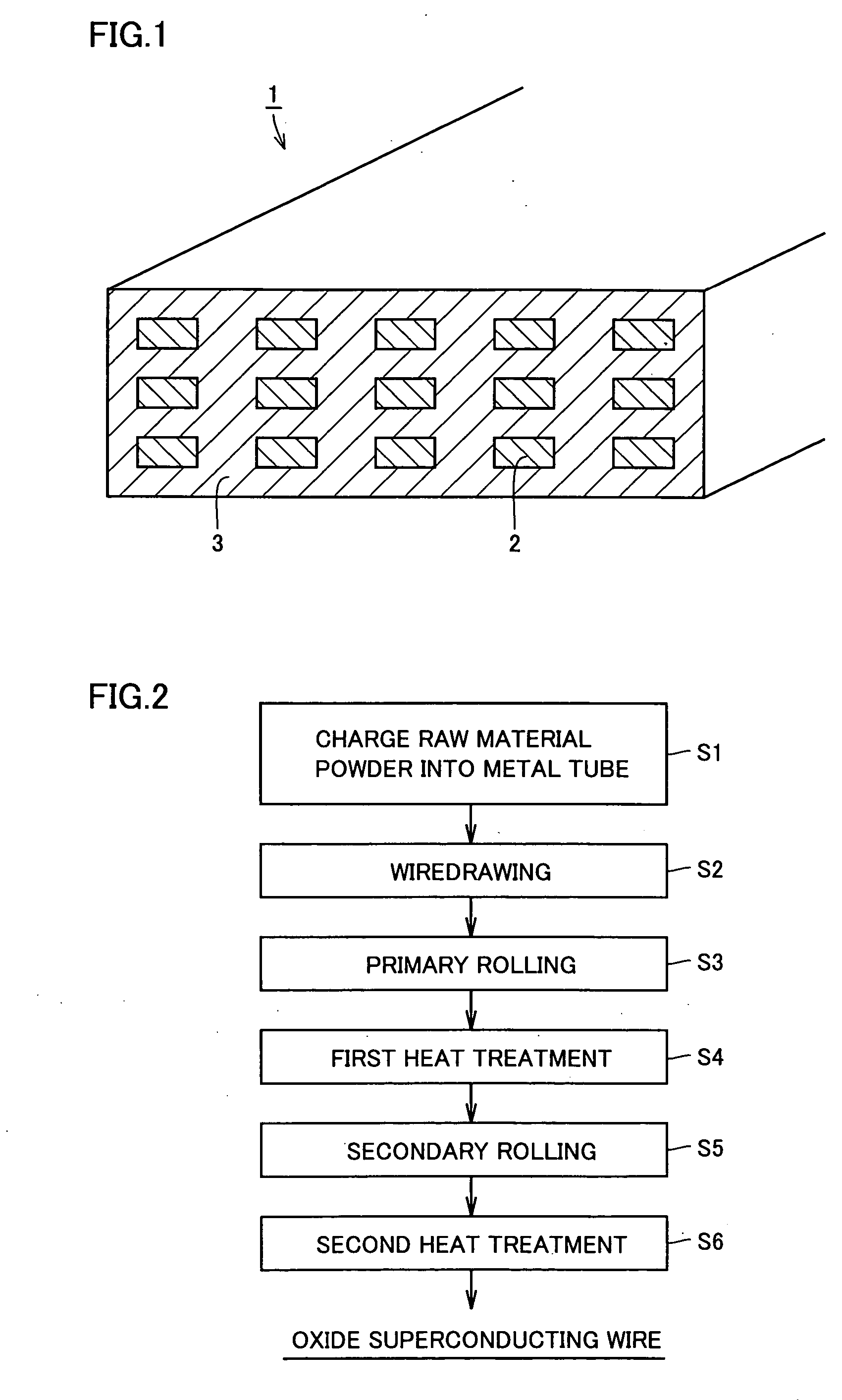
[0077] A multifilamentary oxide superconducting wire, for example, is described with reference to FIG. 1. An oxide superconducting wire 1 has a plurality of oxide superconductor filaments 2 extending in the longitudinal direction and a sheath part 3 covering the same. The material for each of the plurality of oxide superconductor filaments 2 preferably has a Bi--Pb--Sr--Ca--Cu--O composition, for example, and a material including a Bi2223 phase having atomic ratios of (bismuth and lead):strontium:calcium:copper approximately expressed as 2:2:2:3 is optimum in particular. The material for the sheath part 3 consists of silver, for example.

[0078] While a multifilamentary wire has been described in the above, an oxide superconducting wire having a single-core wire structure comprising a single oxide superconductor filament 2 covered with a sheath part 3 may alternatively be employed.

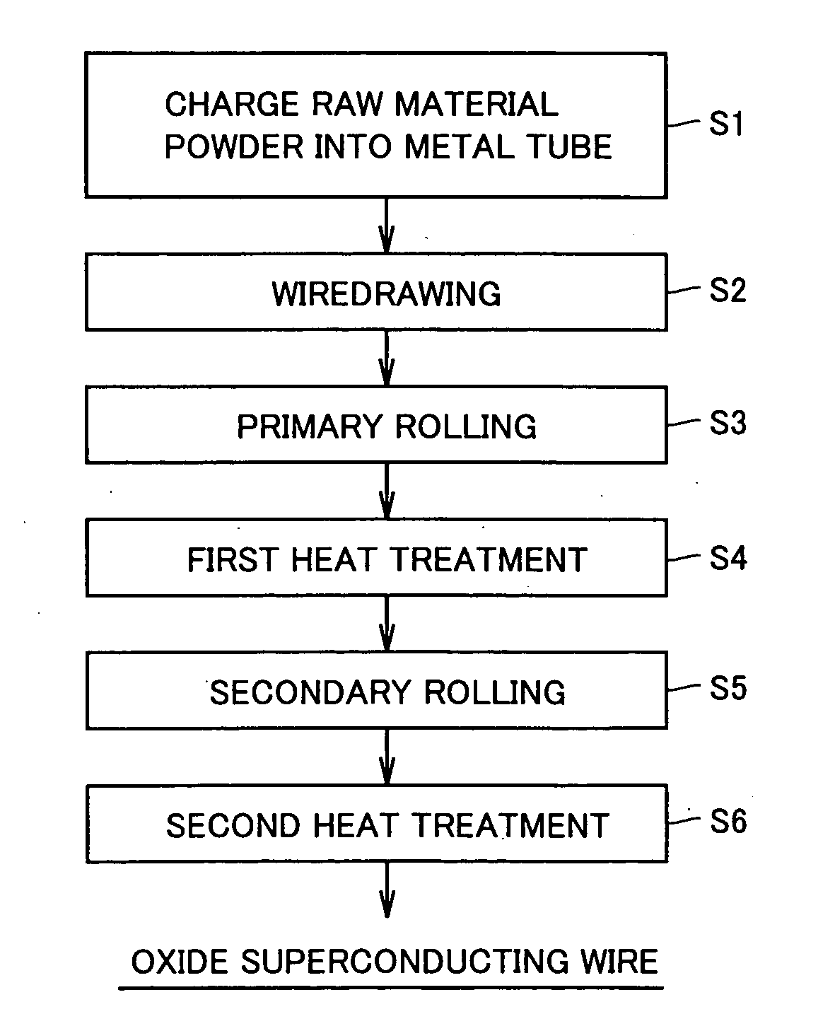
[0079] A method of manufacturing the aforementioned oxide superconducting wire is ...

second embodiment

[0109] Second Embodiment

[0110] Heat treatment conditions in FIGS. 9A and 9B are a total pressure of 20 MPa, a partial oxygen pressure of 0.008 MPa, a temperature of 825.degree. C. in an atmosphere, and a heat treatment time of 50 hours. Referring to FIG. 9A, the thickness of an oxide superconducting wire having no pinholes is reduced by about 0.006 mm to 0.01 mm after a heat treatment. This is because formation of voids between oxide superconducting crystals and blisters of the oxide superconducting wire is suppressed due to the heat treatment in a pressurized atmosphere having the total pressure of 20 MPa. Referring to FIG. 9B, on the other hand, the thickness of an oxide superconducting wire having pinholes is reduced only by about 0.002 mm to 0.005 mm after the heat treatment, and formation of voids between oxide superconducting crystals and blisters of the oxide superconducting wire is not sufficiently suppressed. The thickness of a portion (portion A) having pinholes in the wir...

third embodiment

[0142] Third Embodiment

[0143] In order to further improve the critical current density of the oxide superconducting wire, the inventors have made deep studies as to the optimum partial oxygen pressure at the heat-up time before the heat treatment and in the heat treatment. Thus, results shown in FIG. 17 have been obtained.

[0144] Referring to FIG. 17, it is understood that a stable oxide superconducting phase is formed and the critical current density is improved in a temperature range of at least 815.degree. C. and not more than 825.degree. C. if the partial oxygen pressure is 0.007 MPa, for example. Further, a stable oxide superconducting phase is formed and the critical current density is improved in a temperature range of at least 750.degree. C. and not more than 800.degree. C., preferably in a temperature range larger by at least 770.degree. C. and not more than 800.degree. C. if the partial oxygen pressure is 0.0003 MPa, although this is not shown in the figure. In addition, a ...


PUM

PropertyMeasurementUnit
total pressureaaaaaaaaaa
pressureaaaaaaaaaa

Abstract

The inventive method of manufacturing an oxide superconducting wire comprises a step (S1, S2) of preparing a wire formed by covering raw material powder of an oxide superconductor with a metal and a step (S4, S6) of heat-treating the wire in a pressurized atmosphere, and the total pressure of the pressurized atmosphere is at least 1 MPa and less than 50 MPa. Thus, formation of voids between oxide superconducting crystals and blisters of the oxide superconducting wire is suppressed while the partial oxygen pressure can be readily controlled in the heat treatment, whereby the critical current density can be improved.

Description

[0001] The present invention relates to a method of manufacturing an oxide superconducting wire, and more particularly, it relates to a method of manufacturing an oxide superconducting wire from a wire formed by covering raw material powder of an oxide superconductor with a metal.BACKGROUND TECHNIQUE[0002] In general, a method of obtaining an oxide superconducting wire by heat-treating a wire formed by charging a metal tube with raw material powder of an oxide superconductor and thereafter wiredrawing and rolling the metal tube for sintering the raw material powder of the oxide superconductor is known as a method of manufacturing an oxide superconducting wire. However, the wire is blistered in the aforementioned heat treatment step for sintering, to disadvantageously reduce the superconductivity of the obtained oxide superconducting wire.[0003] Japanese Patent Laying-Open No. 5-101723 proposes a method of manufacturing an oxide superconducting wire by heat-treating a metal tube char...

Claims


Application Information

Patent Timeline
Patent Type & Authority Applications(United States)
IPC IPC(8): H01B13/00H01L39/24H01R43/00
CPCH01L39/248Y10T29/49014Y10T29/49222Y10T29/49194Y10T29/49117H10N60/0801H01B12/00H01B13/00
Inventor KOBAYASHI, SHIN-ICHIKATO, TAKESHI
Owner SUMITOMO ELECTRIC IND LTD
Why Eureka
Try Eureka