Method for moving a fluid of interest in a capillary tube and fluidic microsystem

a fluid and microsystem technology, applied in the field of capillary tubes and fluid microsystems, can solve the problems of imposing certain constraints on the physicochemical properties, the precision of these systems, and the addition of the problem of biological contamination of one slug by another

Inactive Publication Date: 2004-12-02
COMMISSARIAT A LENERGIE ATOMIQUE ET AUX ENERGIES ALTERNATIVES
View PDF7 Cites 65 Cited by
  • Summary
  • Abstract
  • Description
  • Claims
  • Application Information

AI Technical Summary

Problems solved by technology

One of the most serious problems to be solved for the implementation of this novel microchannel technology is the issue of how to control fluid flow or transport within the microchannels.
In addition, the increase in analyser flow rates could require the stacking in series along the microchannels of several different reactive liquids in the form of slugs, which then adds the problem of biological contamination of one slug by another.
Certain techniques in the prior art propose the use of variable surface states as a means of flow regulation whilst, however, imposing certain constraints on the physicochemical properties of the fluids to be transported and a precisely defined treatment of the surfaces.
Unfortunately, apart from the lack of precision of these systems, and the difficulty of implementing them, none of them solves the aforementioned problems of the prior art.

Method used


Image

  • Method for moving a fluid of interest in a capillary tube and fluidic microsystem
  • Method for moving a fluid of interest in a capillary tube and fluidic microsystem
  • Method for moving a fluid of interest in a capillary tube and fluidic microsystem

Examples


first embodiment

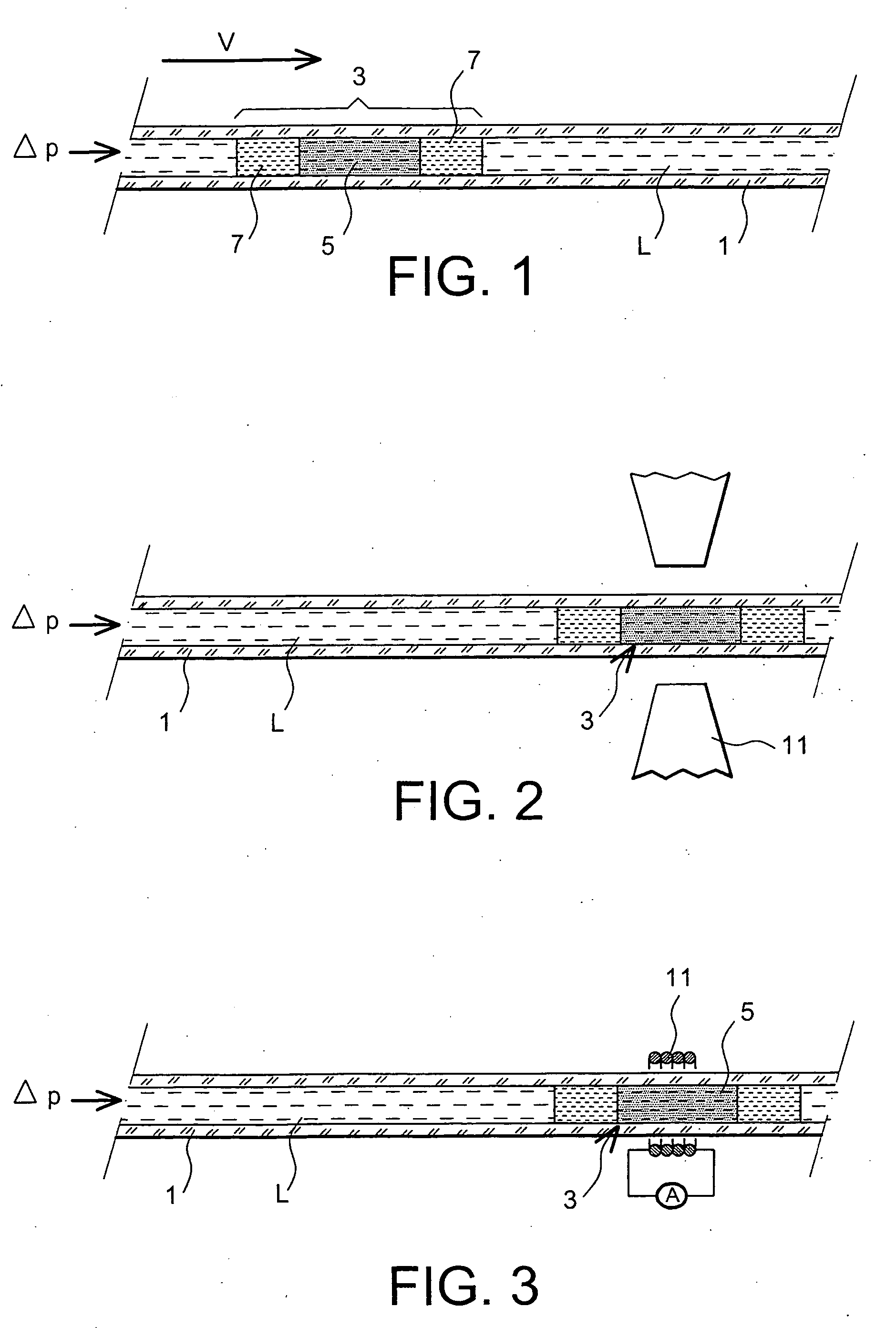
[0033] According to the present invention, the ferrofluid train may be composed of one ferrofluid slug and one slug of liquid immiscible with both the ferrofluid and the analyte fluid. This embodiment is, for example, useful for displacing an analyte fluid placed on one side of the ferrofluid train only, that is on the side of the immiscible liquid.

second embodiment

[0034] According to the present invention, a slug of liquid immiscible with both the ferrofluid and the analyte fluid is placed at each of the two ends of the ferrofluid slug. Thus, in this embodiment, the ferrofluid train comprises one ferrofluid slug and two slugs of liquid immiscible with both the ferrofluid and the analyte fluid. This embodiment is, for example, useful for displacing an analyte fluid placed on either side of the ferrofluid train, or for two different analyte fluids separated by the ferrofluid train.

third embodiment

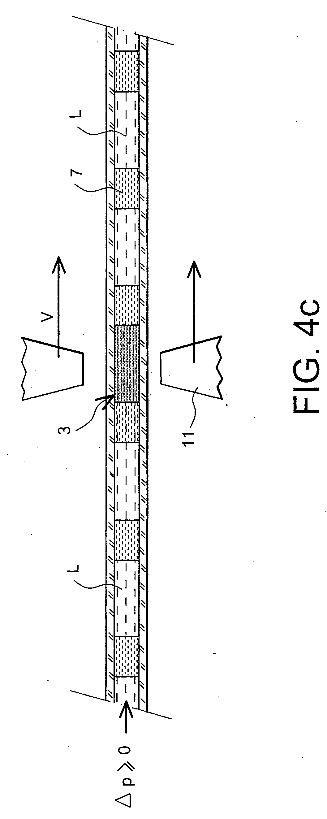
[0035] According to the present invention, a plurality of ferrofluid trains can be introduced into the capillary channel with either identical ferrofluids or ferrofluids that differ from one train to another, and with slugs of liquid immiscible with both the ferrofluid and the analyte fluid being either identical or different in a given train or from one train to another. This embodiment is, for example, useful for displacing several slugs of one or more identical or different analyte fluids, each slug of analyte fluid being separated from the next either by a ferrofluid train according to the present invention or by a single slug of liquid immiscible with both the ferrofluid and the analyte fluid.

[0036] Further embodiments of the present invention will be apparent to those skilled in the art.

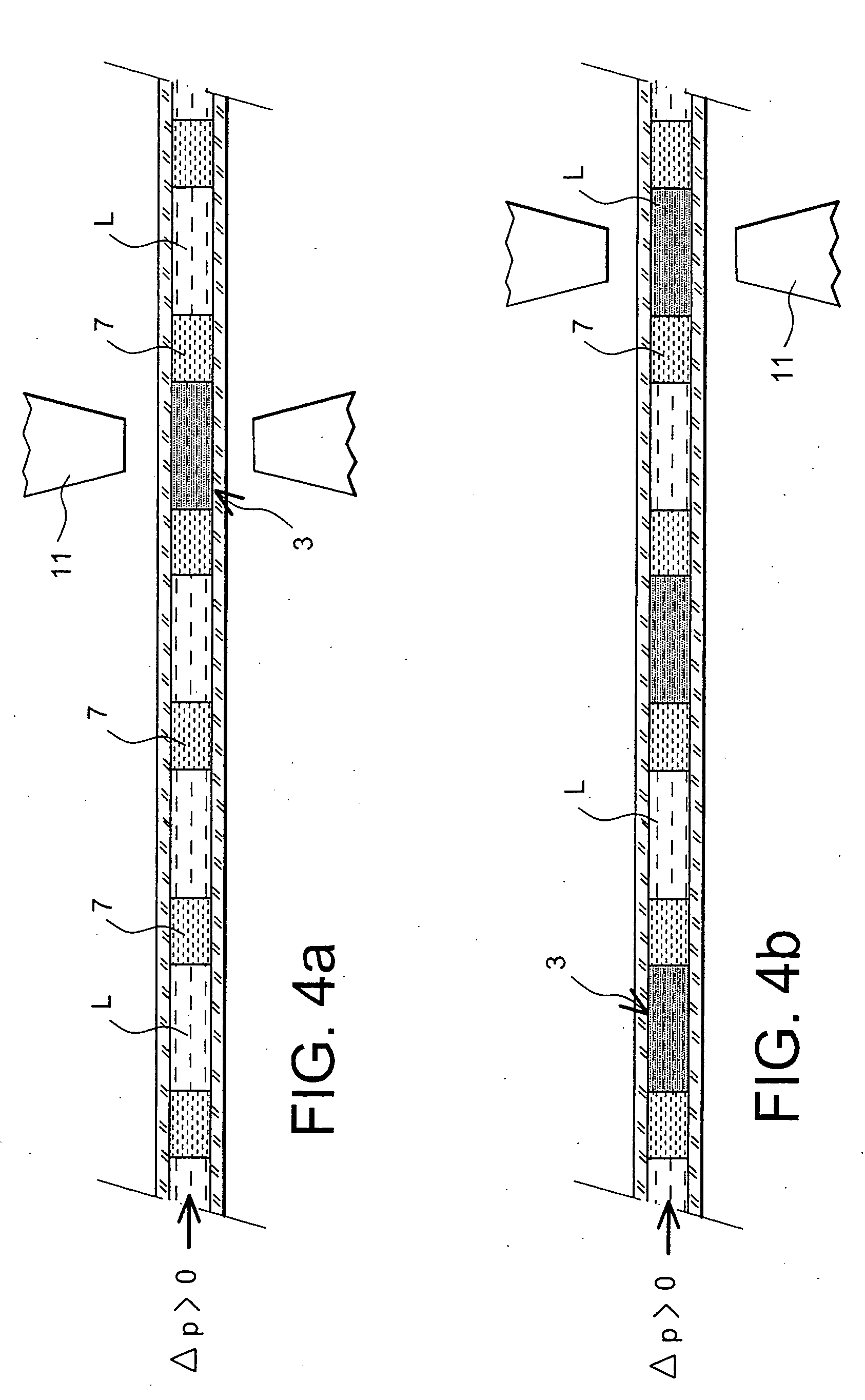
[0037] According to the invention, the magnet system required for displacing the analyte fluid through the capillary channel, in other words for driving the flow of this fluid, may be formed by...


PUM

PropertyMeasurementUnit
diameteraaaaaaaaaa
fluid displacement velocitiesaaaaaaaaaa
thicknessaaaaaaaaaa

Abstract

The present invention relates to a method for the displacement of an analyte fluid within a capillary microchannel and to a microfluidic system. In particular, it relates to the field of microfluidics, and especially to microfluidic systems. The method comprises steps which consist in introducing at least one ferrofluid train (3) into the said capillary channel (1), the said ferrofluid train (3) comprising a slug of ferrofluid (5) and, placed against at least one of the two ends of the slug of ferrofluid and in contact with it, a slug of liquid (7) immiscible with both the ferrofluid and the analyte fluid; in introducing the said analyte fluid (9) into the said capillary channel, in proximity to the ferrofluid train and on the side having the slug of liquid (7) immiscible with both the ferrofluid and the analyte fluid; and in controlling the analyte fluid displacement within the said capillary channel by the action of a magnetic field on the ferrofluid train, which field is generated by a magnet system placed on the outside of the said capillary channel.

Description

[0001] The present invention relates to a method for the displacement of an analyte fluid within a capillary channel and to a microfluidic system.[0002] It relates in particular to the field of microfluidics, and especially to microfluidic systems. It makes it possible to perform chemical or biological processes with high throughputs.[0003] By using microtechnology process techniques it also allows for integration into devices currently referred to as "lab-on-a-chip" and also "micro-Total-Analysis-Systems" or MicroTAS.[0004] In the lab-on-a-chip example, the present invention may be combined with other functions in order to form a more complete and more accurate biological analysis system.PRIOR ART[0005] The development and utilisation of microfluidic systems for obtaining chemical or biological analytical information has shown continuous growth in recent years.[0006] One of the most serious problems to be solved for the implementation of this novel microchannel technology is the is...

Claims


Application Information

Patent Timeline
Patent Type & Authority Applications(United States)
IPC IPC(8): G01N35/08B01L3/00G01N37/00
CPCB01L3/502784B01L2200/0673B01L2400/043H01F1/447H01F21/06
Inventor RICOUL, FLORENCEBERTHIER, JEANBOUTET, JEROME
Owner COMMISSARIAT A LENERGIE ATOMIQUE ET AUX ENERGIES ALTERNATIVES
Why Eureka
Try Eureka