Distributed direct fluid contactor

Inactive Publication Date: 2004-12-09
HAGEN DAVID L +5
View PDF0 Cites 37 Cited by
  • Summary
  • Abstract
  • Description
  • Claims
  • Application Information

AI Technical Summary

Problems solved by technology

Slowly flowing fluids are often laminar, making it difficult to uniformly mix sprays with flows.
Flows are often injected rapidly to cause turbulence to increase mixing.
However it is still difficult to achieve large scale mixing fluids between the center and periphery of flows.
However such measures create pressure drops and corresponding pumping losses.
Pumping losses for gases are substantial.
Compressing gas typically results in losses about 11% of compression power or more due to compressor (turbomachinery) inefficiencies.
These compression losses are compounded at higher pressures where such compressors are staged in sequence.
Parasitic pumping costs for liquids also become significant at higher pressures currently being used e.g., The latest

Method used


Image

  • Distributed direct fluid contactor
  • Distributed direct fluid contactor
  • Distributed direct fluid contactor

Examples


Embodiment Construction

[0043] 4.1 Summary

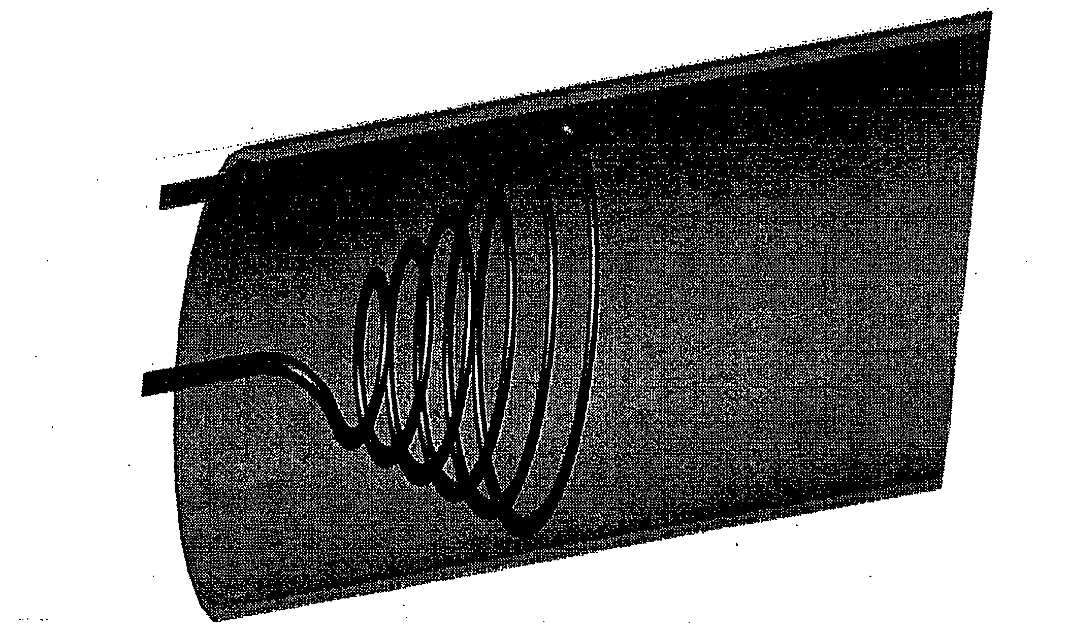
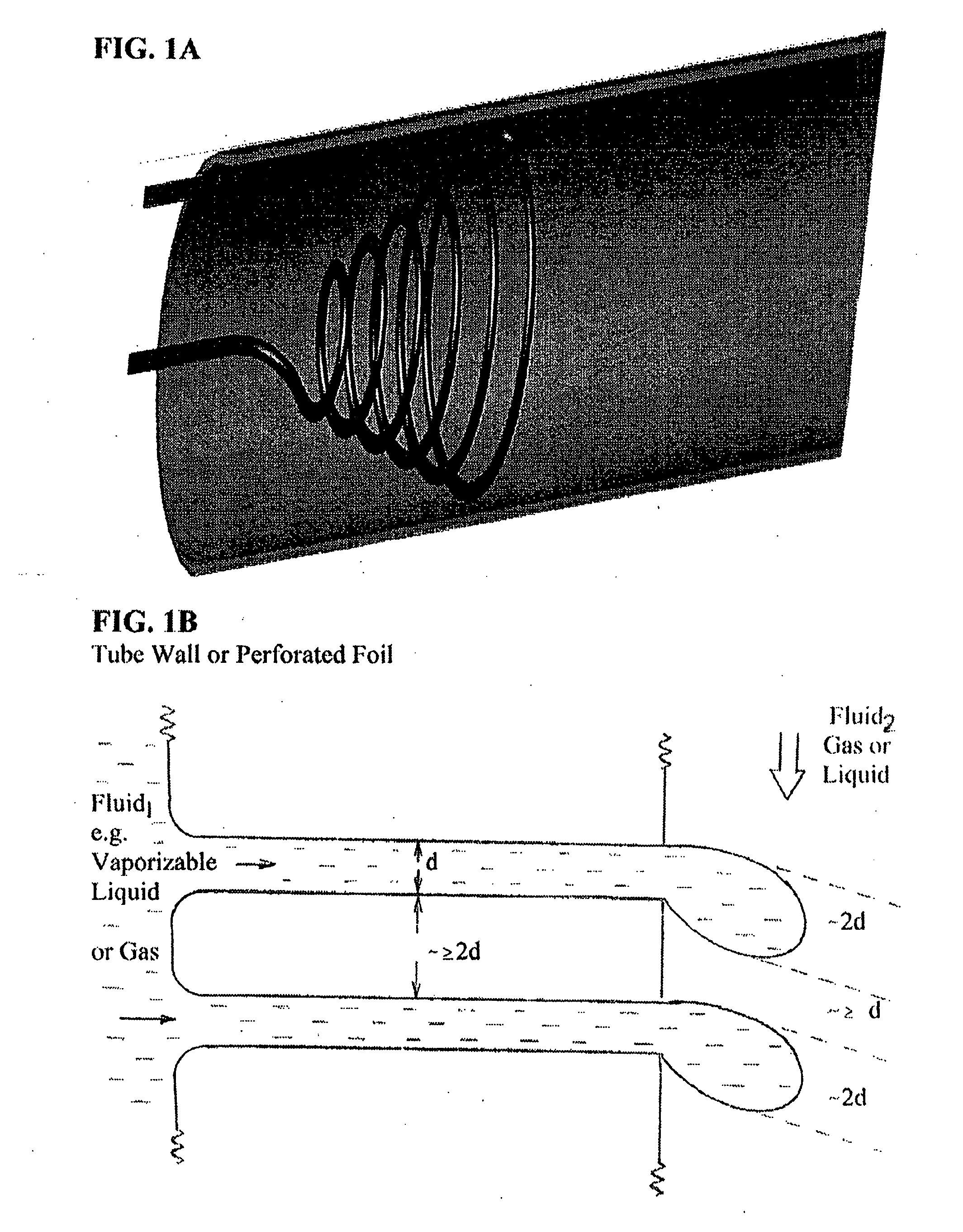
[0044] In some embodiments, users form arrays of streamlined perforated tubes distributed across a flow to efficiently contact one or more fluids flowing through one or more tubes with a second fluid flowing across the tubes.

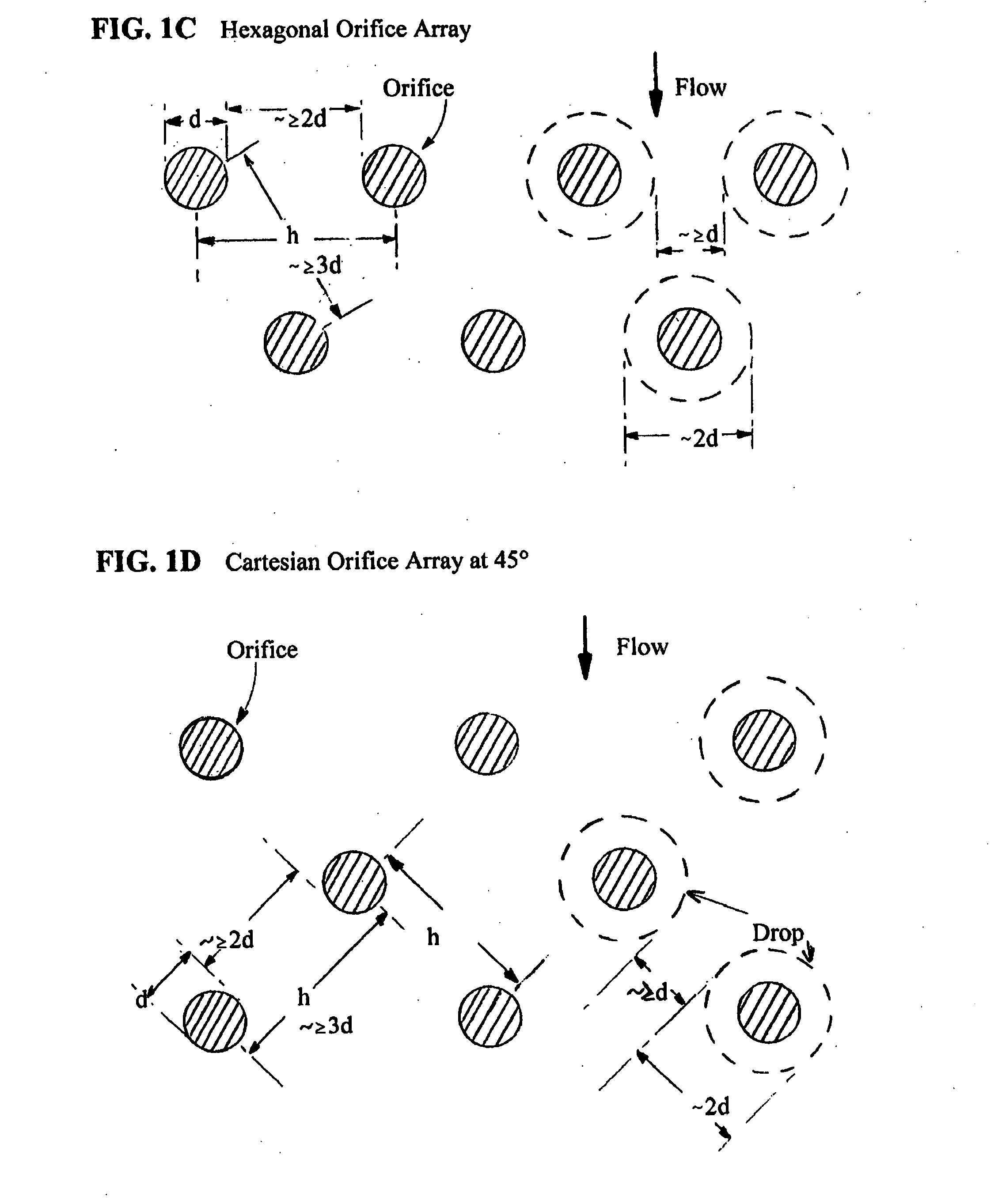
[0045] In some embodiments, users form precise arrays of orifices of uniform size or prescribed, predetermined or pre-selected sizes about and along thin wall or ultra-thin wall tubes.

[0046] In some embodiments, users preferably prepare compound perforated tubes to form smaller orifices. Users preferably form structural upstream tube sections. Users then form perforated downstream tube sections from thin strips or foils and bond these to the structural sections.

[0047] In some embodiments, users form arrays of perforated tubes attached to supply manifolds. Users preferably offset adjacent tubes upstream / downstream to increase flow area between tubes and reduce the pressure drop across the array. Users preferably streamline the tube's shape (upst...


PUM


Abstract

The invention relates in general to methods of controlled mixing one fluid with another. In particular it relates to a distributed direct fluid contactor including arrays of streamlined perforated tubes distributed across a flow to efficiently contact and mix one or more fluids flowing through one or more tubes with a second fluid flowing across those tubes. These distributed contactors thereby mix the fluids in a substantially uniform fashion causing a prescribed uniformity or variation in the ratio of the first to second fluid across the space. This thereby to generally creates and controls the physical and/or chemical changes in those fluids, including evaporation, condensation, forming powders and conducting chemical reactions including combustion.

Description

[0001] The invention relates in general to methods of controlled mixing one fluid with another and thereby to generally create and control physical and / or chemical changes in those fluids, including evaporation, condensation, forming powders and conducting chemical reactions including combustion.REFERENCES[0002] 2.1 U.S. Pat. No. 3,651,641 to Ginter, James Lyle; ENGINE SYSTEM AND THERMOGENERATOR THEREFORE, Mar. 28, 1972[0003] 2.2 U.S. Pat. No. 5,617,719 to Ginter, James Lyle; VAPOR-AIR STEAM ENGINE, Apr. 8, 1997[0004] 2.3 U.S. Pat. No. 5,743,080 to Ginter, James Lyle; VAPOR-AIR STEAM ENGINE, Apr. 28, 1998[0005] 2.4 U.S. Pat. No. 6,289,666 to Ginter, James Lyle; HIGH EFFICIENCY LOW POLLUTION HYBRID BRAYTON CYCLE COMBUSTOR, Sep. 18, 2001[0006] 2.5 U.S. Pat. No. 5,031,581 to Powell, Brian; CRANKLESS RECIPROCATING MACHINE, Jul. 16, 1991[0007] 2.6 U.S. Pat. No. 5,570,670 to Powell, Brian; TWO STROKE INTERNAL COMBUSTION ENGINE, Nov. 5, 1996[0008] 2.7 U.S. Pat. No. 6,263,661 to van der Bur...

Claims


Application Information

Patent Timeline
IPC IPC(8): F01K21/04F02C3/30F23J15/00F23L7/00
CPCF01K21/047F02C3/30F05D2270/082F05D2270/083F23J15/003Y02E20/344F23L2900/07002F23L2900/07008F23L2900/07009Y02T50/672Y02T50/677F23L7/00Y02T50/60
Inventor HAGEN, DAVID L.GINTER, GARYGOHEEN, BILLMCGUIRE, ALLANRANKIN, JANETGINTER, J. LYELL
Owner HAGEN DAVID L
Why Eureka
Try Eureka