Sputter target

a technology of sputter target and sputter blade, which is applied in the direction of electrolysis components, vacuum evaporation coatings, coatings, etc., can solve the problems of poor bonding between individual grains, high porous structure of sputter targets, and high cost, and achieve the effect of facilitating the removal of the top layer

Inactive Publication Date: 2004-12-16
NV BEKAERT SA
View PDF3 Cites 21 Cited by
  • Summary
  • Abstract
  • Description
  • Claims
  • Application Information

AI Technical Summary

Benefits of technology

0095] The release layer may for example avoid that a diffusion layer is formed between the target material and the top la

Problems solved by technology

Sprayed zinc targets as for example zinc targets show the disadvantage of forming highly porous structures.
Zinc targets obtained by casting te

Method used


Image

  • Sputter target
  • Sputter target
  • Sputter target

Examples


Embodiment Construction

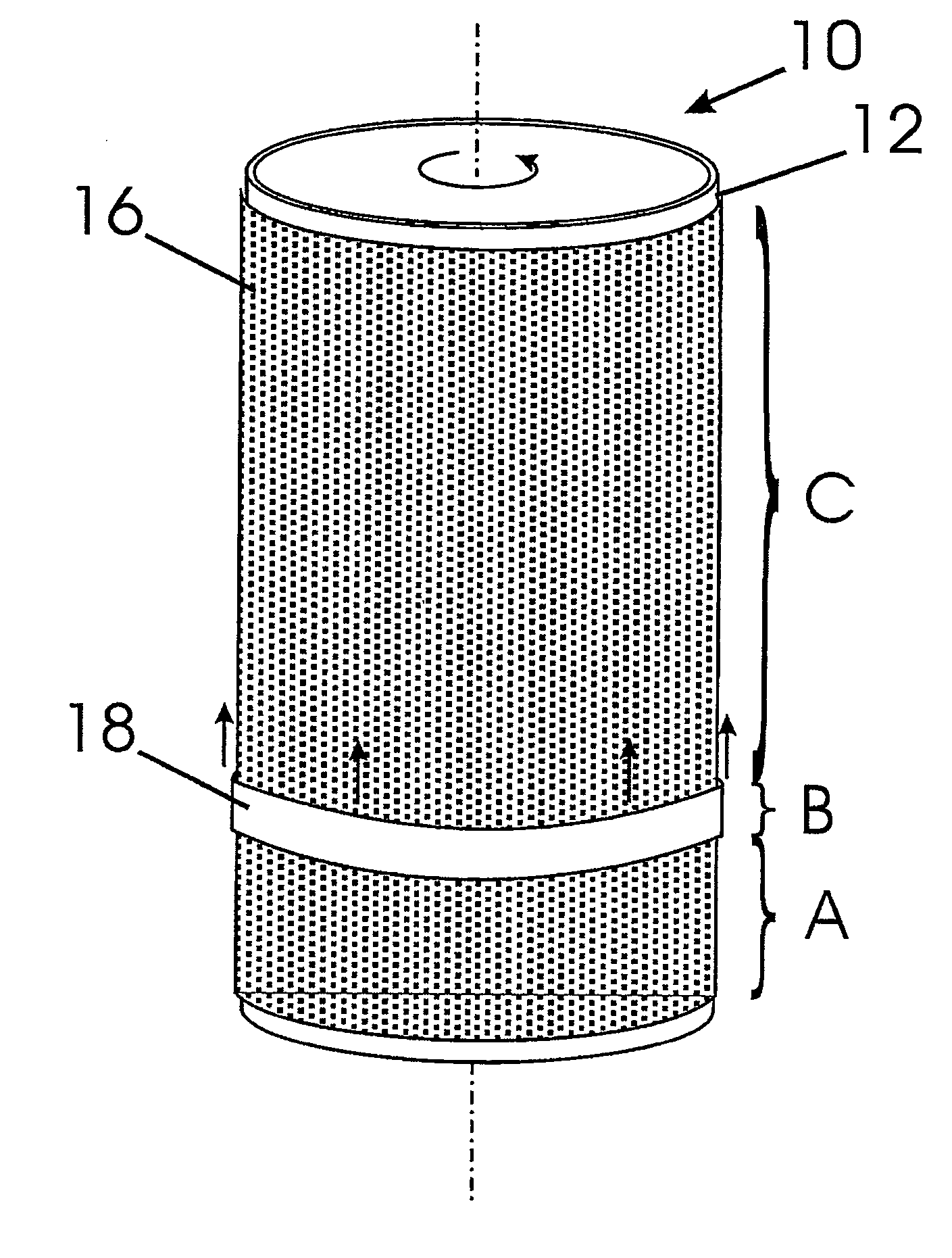
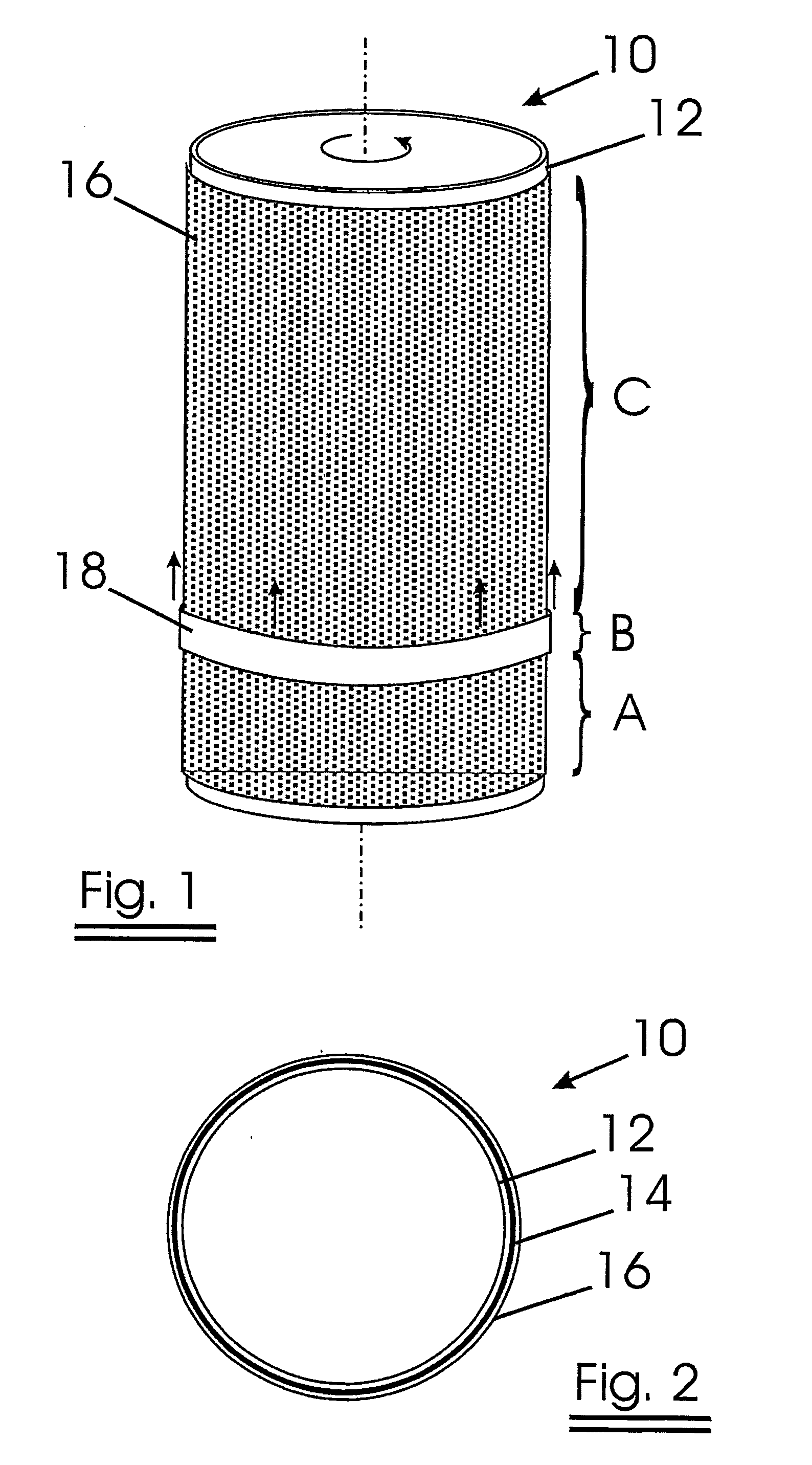
[0099] Referring to FIG. 1, the manufacturing process of a target according to the present invention is explained. FIG. 2 shows the cross-section of a sputter target according to the present invention.

[0100] In a first step a target assembly 10 is manufactured as follows: A layer of target material 14 comprising zinc is sprayed on a stainless steel tube 12. The sprayed zinc layer has a density of about 91%. The zinc layer will function as target material.

[0101] Possibly, the zinc layer comprises one or more doping elements such as Al, Bi, Ce, Gd, Nb, Si, Ti, V, Y, Zr, Sn, Sb.

[0102] The doping element or elements can be added to the target material in an easy way, for example by adding powder.

[0103] Upon the zinc layer, a top layer 16 of stainless steel is applied by spraying.

[0104] The top layer 16 surrounds the target material 14 completely.

[0105] An induction heating coil 18 is disposed around the target assembly so that a molten zone B is created.

[0106] It is preferred that the t...


PUM

PropertyMeasurementUnit
Fractionaaaaaaaaaa
Fractionaaaaaaaaaa
Fractionaaaaaaaaaa

Abstract

The invention relates to a sputter target and more particularly to a zinc sputter target. The target comprises a target holder having an outer surface and a target material formed on said outer surface. The target material has a relative density higher than 92% of the theoretical density of the metal or metal alloy. Furthermore the invention relates to a process for the manufacturing of a sputter target.

Description

FIELD OF THE INVENTION[0001] The invention relates to a sputter target and more particularly, to a zinc sputter target.[0002] Furthermore the invention relates to a process for the manufacturing of a sputter target.BACKGROUND OF THE INVENTION[0003] A target assembly conventionally comprises a target holder, such as a plate or tube, carrying a layer of a target material applied to its outer surface.[0004] Thermal spraying techniques are often employed to apply the target material onto the target holder. In some other cases, the metal target material is cast on a target holder.[0005] Sprayed zinc targets as for example zinc targets show the disadvantage of forming highly porous structures.[0006] Zinc targets obtained by casting techniques are characterised by a somewhat higher density, but they have the disadvantage that the bonding between individual grains may be poor.SUMMARY OF THE INVENTION[0007] It is an object of the present invention to provide an improved target avoiding the d...

Claims


Application Information

Patent Timeline
IPC IPC(8): C23C2/26C23C4/08C23C4/18C23C14/34C23C26/00
CPCC23C2/26C23C4/18C23C14/3414C23C26/00Y02T50/67C23C14/34Y02T50/60
Inventor DE BOSSCHER, WILMERTDELRUE, HILDEVANDERSTRAETEN, JOHAN
Owner NV BEKAERT SA
Why Eureka
Try Eureka