Organic rankine cycle system for use with a reciprocating engine

a technology of organic rankine and reciprocating engine, which is applied in the direction of steam engine plants, machines/engines, mechanical equipment, etc., can solve the problems of large percentage of commercial engines rejecting waste heat, orc working fluid no longer being circulated through the reciprocating engine, and nitrous oxides (nox) and particulates can be an issue, so as to reduce the amount of heat that is transferred and reduce the risk of cavitation

Inactive Publication Date: 2004-12-23
INT FUEL CELLS +1
View PDF31 Cites 34 Cited by
  • Summary
  • Abstract
  • Description
  • Claims
  • Application Information

AI Technical Summary

Benefits of technology

[0013] In accordance with another aspect of the invention, a bypass arrangement is provided to bypass the ORC turbo generator such that the flow of coolant passes directly from the evaporator / boiler to the condenser, and also to divert the reciprocating engine hot exhaust gases from the evaporator. This reduces the amount of heat that is transferred to the refrigerant and allows for a smaller pump to be used as the auxiliary pump.
[0014] By yet another aspect of the invention, provision is made for simultaneous operation of two pumps in series, a primary and an auxiliary pump during normal operation such that the speed of both pumps can be reduced to thereby reduce the risk of cavitation.

Problems solved by technology

However, atmospheric emissions such as nitrous oxides (NOx) and particulates can be an issue with reciprocating engines.
However, commercial engines reject a large percentage of their waste heat through intake after coolers, coolant jacket radiators, and oil coolers.
One problem that the applicants have recognized in such a system is that, if the organic rankine cycle (ORC) is disabled by component failure or for planned maintenance, the ORC working fluid will no longer be circulated through the reciprocating engine and the temperature of the ORC working fluid inside the engine as well as the critical engine components being cooled by this fluid will quickly exceed the safe level point of about 200.degree. F., and it becomes then necessary to shut down the engine and cease operation.
However, such a pump is subject to cavitation especially since it is downstream of the condenser where the liquid from the condenser is only slightly subcooled.

Method used


Image

  • Organic rankine cycle system for use with a reciprocating engine
  • Organic rankine cycle system for use with a reciprocating engine
  • Organic rankine cycle system for use with a reciprocating engine

Examples


Embodiment Construction

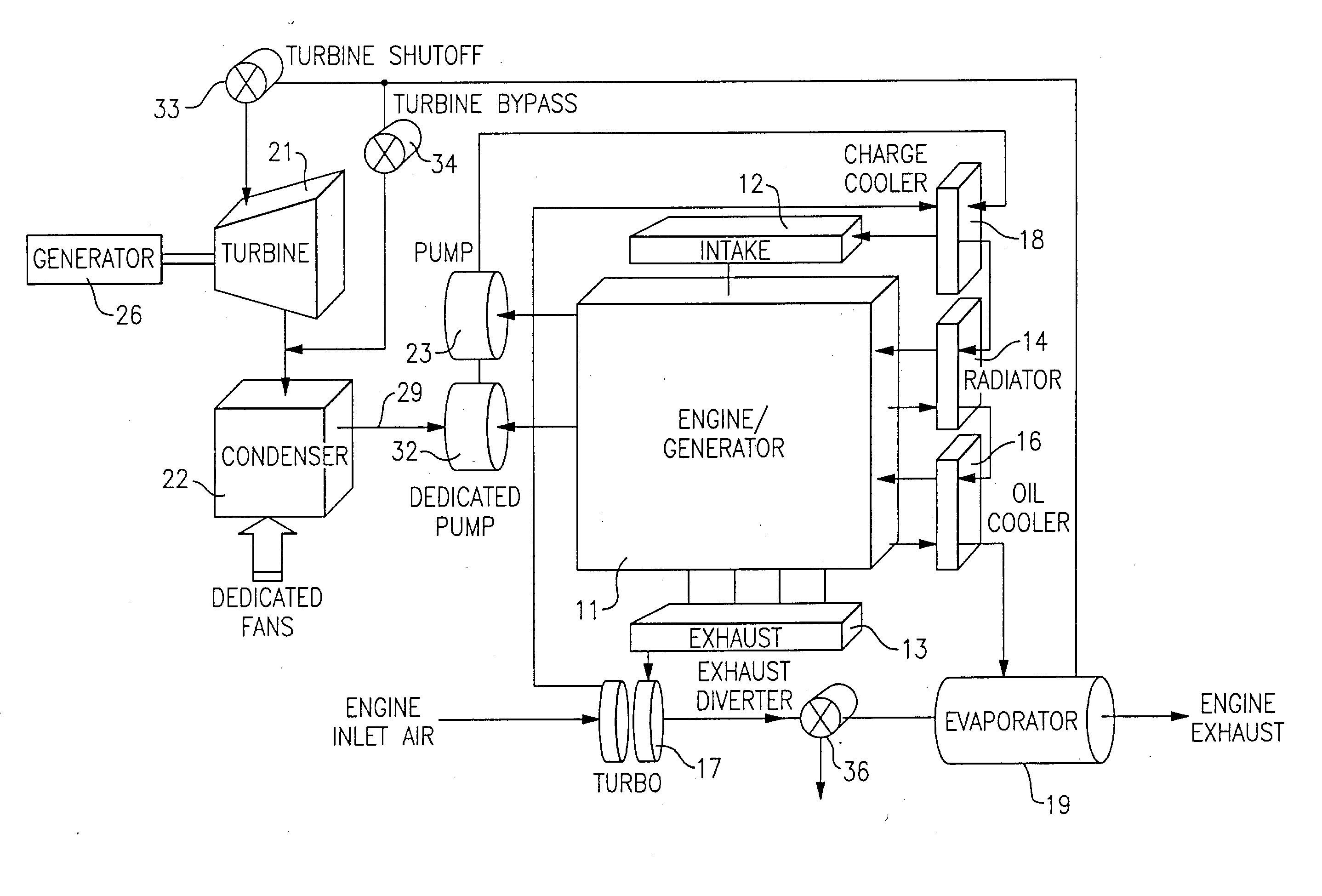
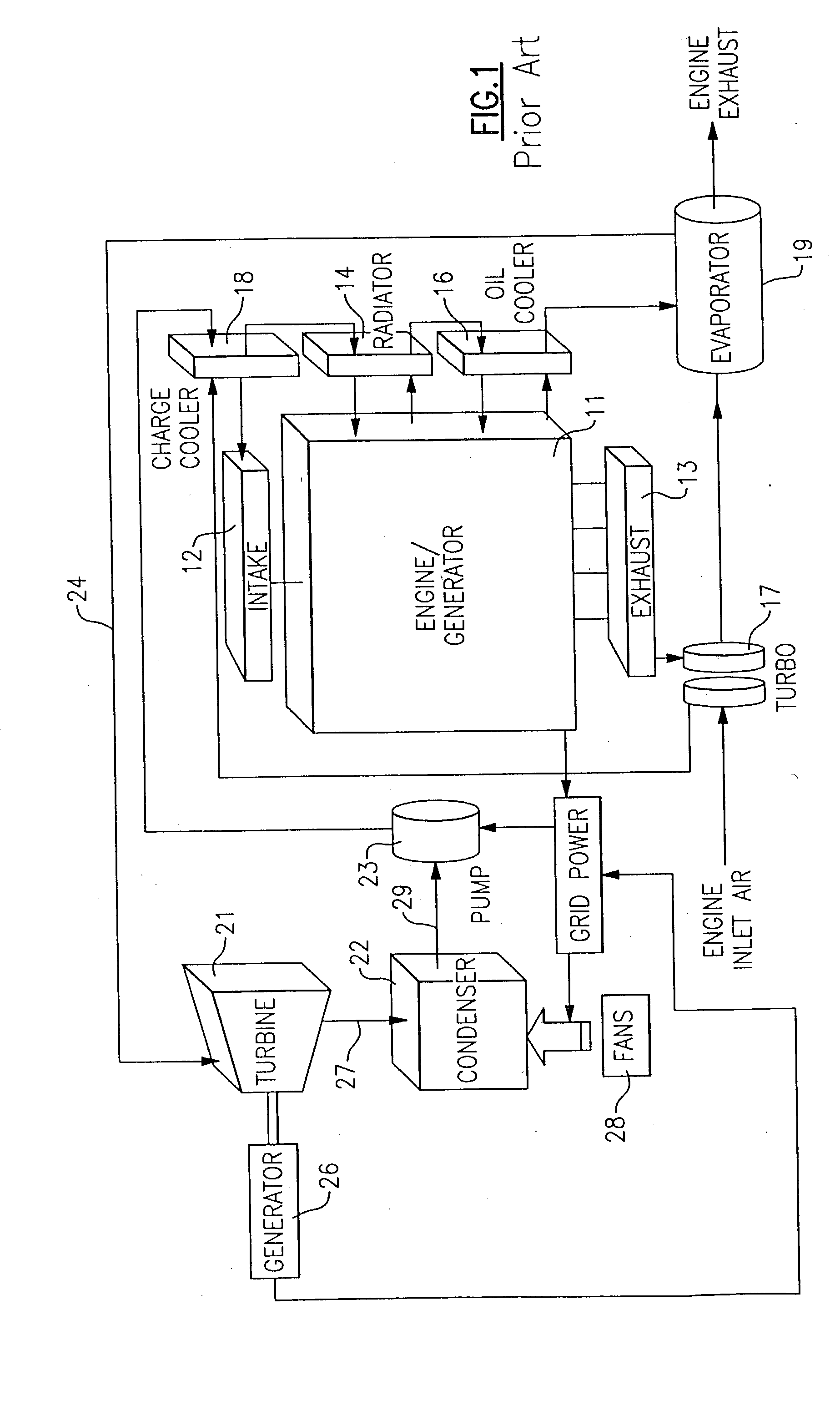
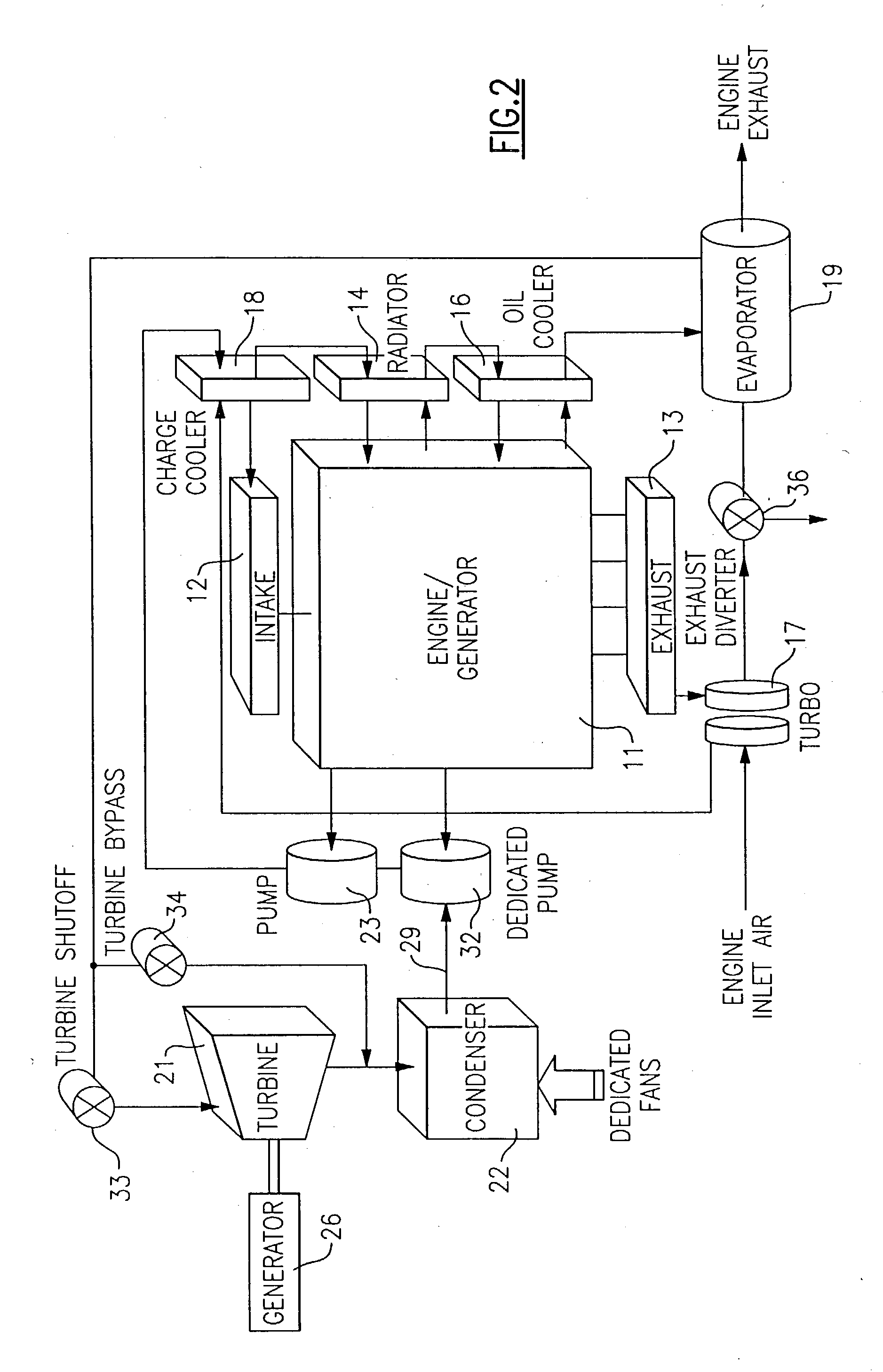
[0018] Referring now to FIG. 1, there is shown a reciprocating engine 11 of the type which is typically used to drive a generator (not shown) for purposes of providing electrical power for consumer use. The engine 11 has an air intake section 12 for taking in air for combustion purposes and an exhaust 13 which may be discharged to the environment, but is preferably applied to convert a portion of the energy therein to useful purposes.

[0019] The engine 11 also has a plurality of heat exchangers with appropriate fluid for maintaining the engine 11 at acceptable operating temperatures. A radiator 14 is provided to take heat away from a liquid coolant that is circulated in heat exchange relationship with the portion of the engine where combustion occurs, while an oil cooler 16 is provided to remove heat from a lubricant that is circulated within the moving parts of the engine 11.

[0020] The engine 11 may be provided with a turbo charger 17 which receives high temperature, high pressure e...


PUM


Abstract

In a waste heat recovery system wherein an organic rankine cycle system uses waste heat from the fluids of a reciprocating engine, provision is made to continue operation of the engine even during periods when the organic rankine cycle system is inoperative, by providing an auxiliary pump and a bypass for the refrigerant flow around the turbine. Provision is also made to divert the engine exhaust gases from the evaporator during such periods of operation. In one embodiment, the auxiliary pump is made to operate simultaneously with the primary pump during normal operations, thereby allowing the primary pump to operate at lower speeds with less likelihood of cavitation.

Description

BACKGROUND OF THE INVENTION[0001] This invention relates generally to waste heat recovery systems and, more particularly, to a organic rankine cycle system for extracting heat from a reciprocating engine.[0002] Power generation systems that provide low cost energy with minimum environmental impact, and which can be readily integrated into the existing power grids or which can be quickly established as stand alone units, can be very useful in solving critical power needs. Reciprocating engines are the most common and most technically mature of these distributed energy resources in the 0.5 to 5 MWe range. These engines can generate electricity at low cost with efficiencies of 25% to 40% using commonly available fuels such as gasoline, natural gas or diesel fuel. However, atmospheric emissions such as nitrous oxides (NOx) and particulates can be an issue with reciprocating engines. One way to improve the efficiency of combustion engines without increasing the output of emissions is to ...

Claims


Application Information

Patent Timeline
Patent Type & Authority Applications(United States)
IPC IPC(8): F01K23/06
CPCF01K23/065
Inventor RADCLIFF, THOMAS D.MCCORMICK, DUANEBRASZ, JOOST J.
Owner INT FUEL CELLS
Why Eureka
Try Eureka