Phosphor converted light emitting device

a light emitting device and phosphor technology, applied in the field of illumination systems, can solve the problems of inability to generate white light of the desired tone, limited use of white light leds based on dichromatic approaches for general-purpose illumination, and difficulty in exploiting the small stokes' shift of lutetium-containing garnet phosphor

Active Publication Date: 2004-12-23
LUMILEDS
View PDF6 Cites 129 Cited by
  • Summary
  • Abstract
  • Description
  • Claims
  • Application Information

AI Technical Summary

Problems solved by technology

When generating white light with an arrangement of red, green and blue light emitting diodes, there has been such a problem that white light of the desired tone cannot be generated due to variations in the tone, luminance and other factors of the light emitting diodes.
However, white light LEDs based on the dichromatic approach can only be used to a limited extent for general-purpose illumination, on account of their poor color rendering caused by the absence of red color components.
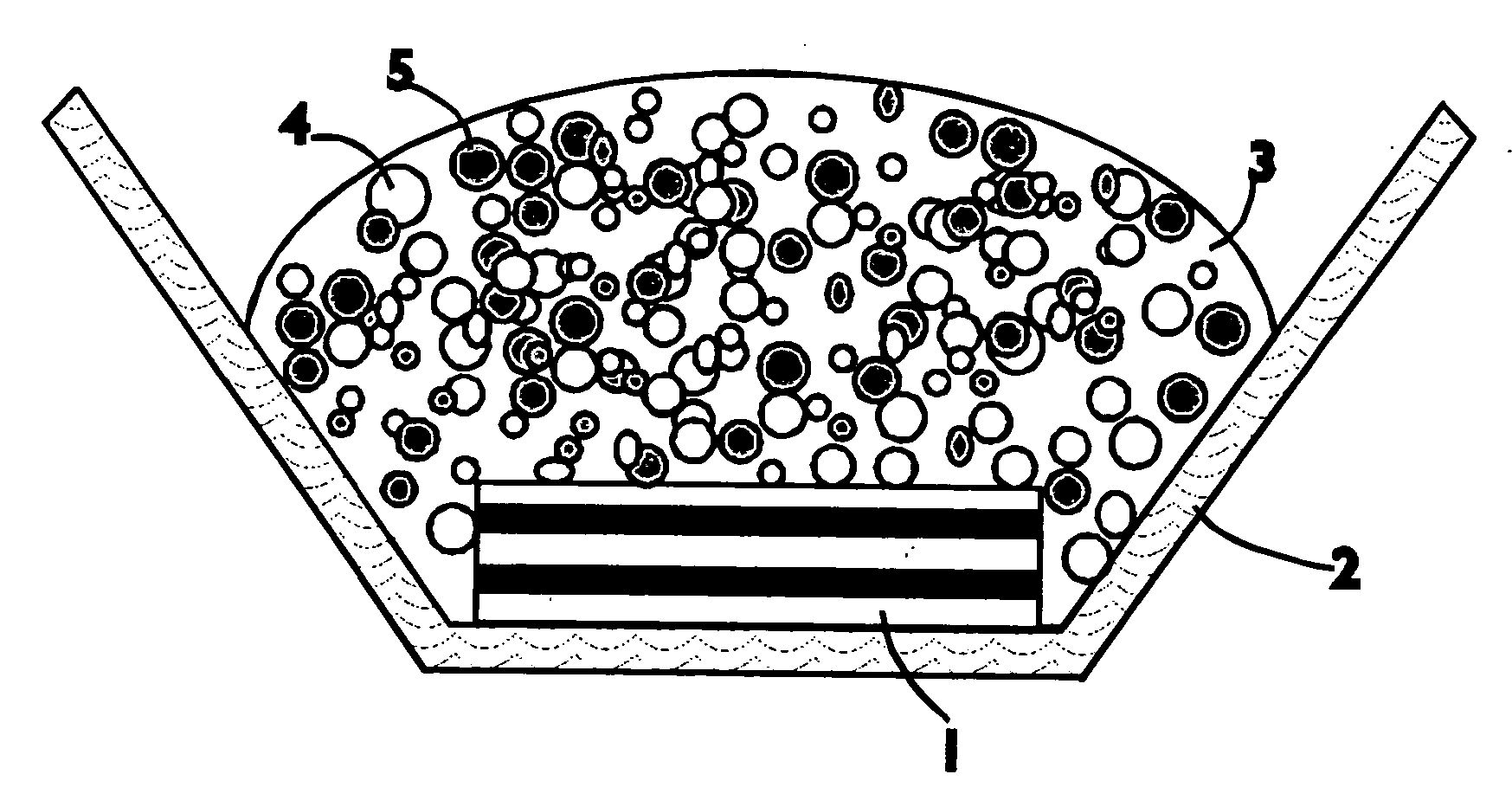
In a device where a red-emitting phosphor is mixed with a lutetium-containing garnet phosphor, such as the device illustrated in FIG. 1, it may be difficult to exploit the small Stokes' shift of the lutetium-containing garnet phosphor since the red-emitting phosphor may absorb a significant portion of the light emitted by the lutetium-containing garnet phosphor.
As a result, when a slurry containing such phosphors is deposited over a device, the lutetium-containing garnet phosphor particles tend to sink quickly, leaving most of the lutetium-containing garnet phosphor close to the device and most of the red-emitting phosphor further from the device.

Method used


Image

  • Phosphor converted light emitting device
  • Phosphor converted light emitting device
  • Phosphor converted light emitting device

Examples


Embodiment Construction

[0064] For the phosphor synthesis of a phosphor of general formula (Lu.sub.1x-y-a-bY.sub.xGd.sub.y).sub.3(Al.sub.1-zGa.sub.z).sub.5O.sub.12:-Ce.sub.aPr.sub.b wherein 0


PUM

PropertyMeasurementUnit
peak emission wavelengthaaaaaaaaaa

Abstract

A system includes a radiation source capable of emitting first light and a fluorescent material capable of absorbing the first light and emitting second light having a different wavelength than the first light. The fluorescent material is a phosphor having the formula (Lu1-x-y-a-bYxGdy)3(Al1-zGaz)5O12:CeaPrb wherein 0<x<1, 0<y<1, 0<z<=0.1, 0<a<=0.2 and 0<b<=0.1. In some embodiments, the (Lu1-x-y-a-bYxGdy)3(Al1-zGaz)5O12:CeaPrb is combined with a second fluorescent material capable of emitting third light. The second fluorescent material may be a red-emitting phosphor, such that the combination of first, second, and third light emitted from the system appears white.

Description

[0001] 1. Field of Invention[0002] The present invention generally relates to an illumination system comprising a radiation source and a fluorescent material comprising a phosphor.[0003] 2. Description of Related Art[0004] Recently, various attempts have been made to make white light emitting illumination systems by using light emitting diodes (LEDs) as radiation sources. When generating white light with an arrangement of red, green and blue light emitting diodes, there has been such a problem that white light of the desired tone cannot be generated due to variations in the tone, luminance and other factors of the light emitting diodes.[0005] In order to solve these problems, there have been previously developed various illumination systems, which convert the color of light emitted by light emitting diodes, by means of a fluorescent material comprising a phosphor to provide a visible white light illumination.[0006] Previous illumination systems have been based in particular either o...

Claims


Application Information

Patent Timeline
Patent Type & Authority Applications(United States)
IPC IPC(8): C09K11/77C09K11/80F21K2/00H01L33/50
CPCC09K11/7774H01L33/502
Inventor MUELLER-MACH, REGINA B.MUELLER, GERD O.JUESTEL, T.BUSSELT, W.SCHMIDT, P. J.MAYR, W.
Owner LUMILEDS
Why Eureka
Try Eureka