Backpressure history mechanism in flow control

a flow control and history technology, applied in the field of backpressure history mechanism in flow control, can solve the problem of large number of queues in the second stage device, and achieve the effect of reducing the amount of traffic, reducing the number of queues needed, and saving queue spa

Inactive Publication Date: 2004-12-23
WSOU INVESTMENTS LLC
View PDF7 Cites 17 Cited by
  • Summary
  • Abstract
  • Description
  • Claims
  • Application Information

AI Technical Summary

Benefits of technology

0027] As the invention eliminates ambiguity in the amount of traffic due to arrive at the queue during the flow control round trip time, the queue can be made not to overflow by performing backpressure flow control scheme based on the amount of due traffic. This will eliminate the necessity of a large head room in the queue.
0028] The saving in the queue space will be compounded as the telecommunications systems are designed to handle a larger mount of traffic and the number of needed queues increases.

Problems solved by technology

The number of queues in the second stage device may be large.
In some cases, a large "T" for a given architecture or a small storage capacity in a stage 2 device may require an intermediate queuing stage between stage 1 and stage 2 or may possibly affect feasibility of a given system design.

Method used


Image

  • Backpressure history mechanism in flow control
  • Backpressure history mechanism in flow control
  • Backpressure history mechanism in flow control

Examples


Embodiment Construction

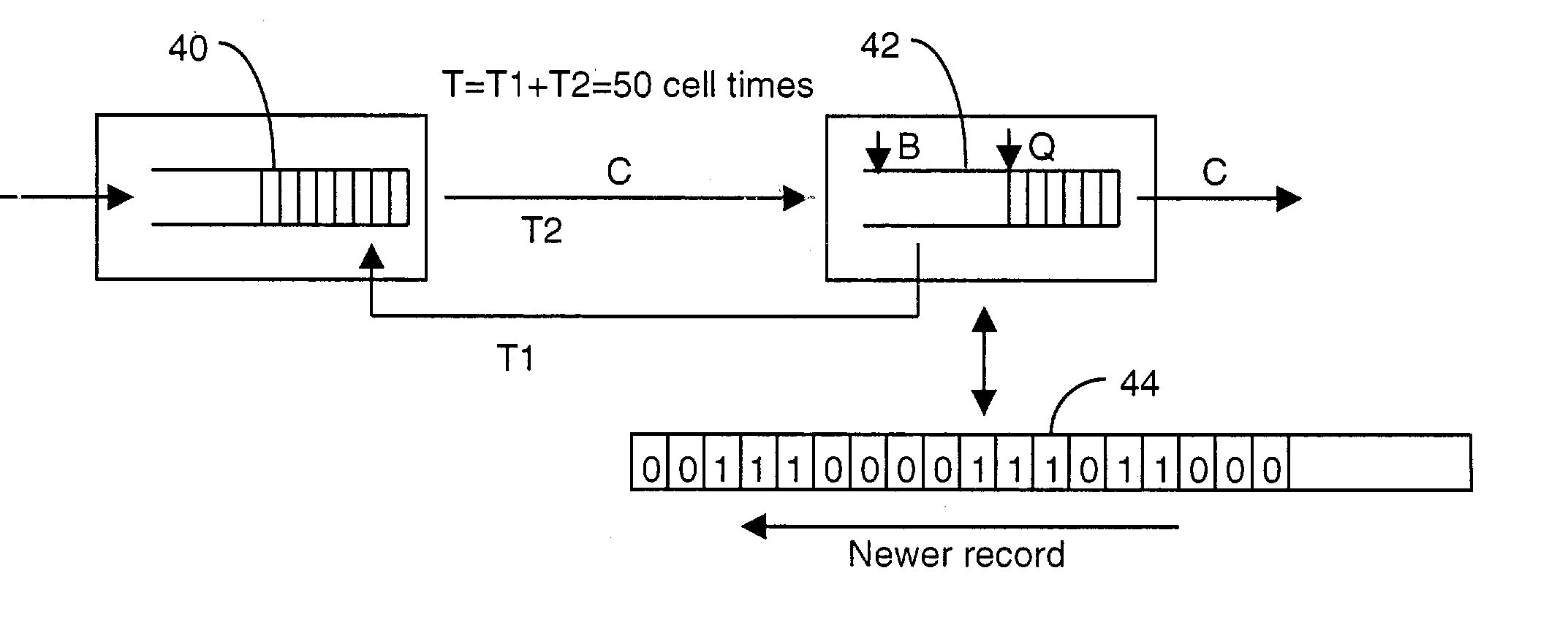
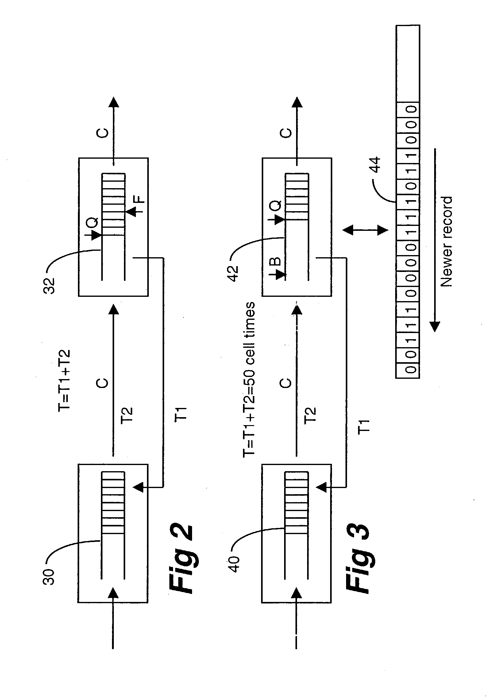
[0039] FIG. 3 shows the invention according to one embodiment. It shows a similar arrangement of queues as those of FIG. 2. It is assumed to have the same parameters as those discussed in connection with FIG. 2. In FIG. 3, first stage queue 40 and second stage queue 42 are shown in which the second stage queue 42 maintains a history list 44 of the backpressure flow control signals. It should be understood that in practice, there are multiple second stage queues and therefore each second stage queue maintains its history list of control signals which are sent to the first stage device. The history list represents a record of the flow control signals over the most recent round trip time T. The units of the history list are some convenient measure of time (e.g. in an ATM cell flow, a single time unit could be the time required to transmit one cell).

[0040] Let Tg represent the total amount of time over the last T that the flow control backpressure signal was in the Go state. Q represent...


PUM


Abstract

The backpressure flow control mechanism is widely used in telecommunications network. Actions of the flow control scheme are not instantaneous in that latency always exists between action and reaction, resulting in a flow control round trip time. This flow control round trip time causes ambiguity in determining the amount of traffic in transit. The invention monitors the amount of traffic which is on the way toward the queue during the past period of the round trip time, thus eliminating the ambiguity. A more precise control of traffic flow is possible, realizing reduction of storage space in the queue by one half. In one embodiment, the invention keeps a historical record of flow control signals sent back during the most recent flow control round trip time.

Description

[0001] The present invention relates generally to a flow control technique for data transmission in telecommunications networks. It relates more specifically to a resource efficient way to control flows of data between two stages of queues.[0002] Telecommunications networks use buffer memories or queues for a wide variety of purposes. In this specification, buffer memories, buffers, queues and FIFOs are used synonymously, as are cells and packets of data. A telecommunications node such as, a switching element, router, multiplexer e.g., statistical multiplexer, receives data packets at a plurality of input ports and transports them to one or more of its appropriate output ports. Queues are often used at the input and output ports to store the packets temporarily while the node processes the packet headers and executes appropriate actions. The queues are also used to regulate the flow of packets between two nodes or between two stages of modules which make up a node or nodes. The move...

Claims


Application Information

Patent Timeline
Patent Type & Authority Applications(United States)
IPC IPC(8): H04L12/56
CPCH04L12/5601H04L47/26H04L47/283H04L49/254H04L49/3081H04L2012/5635H04L2012/5649
Inventor STERNE, JASONDAVIS, TOM EDWARD
Owner WSOU INVESTMENTS LLC
Why Eureka
Try Eureka