Apparatus and method for reception

a technology of apparatus and method, applied in the field of apparatus and method for reception, can solve the problems of deteriorating the quality of the signal obtained through interference cancellation processing on each communication terminal, difficult to apply exact, and inability to thereby perform interference cancellation satisfactorily, etc., to achieve the effect of improving a reception characteristi

Inactive Publication Date: 2004-12-23
PANASONIC CORP
View PDF8 Cites 10 Cited by
  • Summary
  • Abstract
  • Description
  • Claims
  • Application Information

AI Technical Summary

Benefits of technology

0026] It is an object of the present invention to exactly detect signal paths about each communication terminal from received midamble signals and thereby improve a reception characteristic.

Problems solved by technology

However, in a mobile communication system, there is a possibility that paths whose delay time exceeds the time corresponding to the length of a unit midamble shift amount of W may be produced.
When the delay time exceeds the unit midamble shift amount of W, it is difficult to apply exact path detection processing on the signal of each communication terminal and the quality of the signal obtained through interference cancellation processing on each communication terminal deteriorates.
Thereafter, the communication terminal U-1 solves equations for interference cancellation based on such mistakenly recognized path information, and cannot thereby perform interference cancellation satisfactorily.
This deteriorates the quality of signals obtained through interference cancellation processing.
Furthermore, because of the characteristic of a reception filter, part of distorted power of the start sample of the following midamble shift may appear behind the delay profile of the preceding midamble shift.
In this case, if paths are selected regarding all of them as power values in the own delay profile, path distortion components in the delay profile of the other midamble shift may be selected as the own paths, which leads to deterioration of a demodulation characteristic.

Method used


Image

  • Apparatus and method for reception
  • Apparatus and method for reception
  • Apparatus and method for reception

Examples


embodiment 1

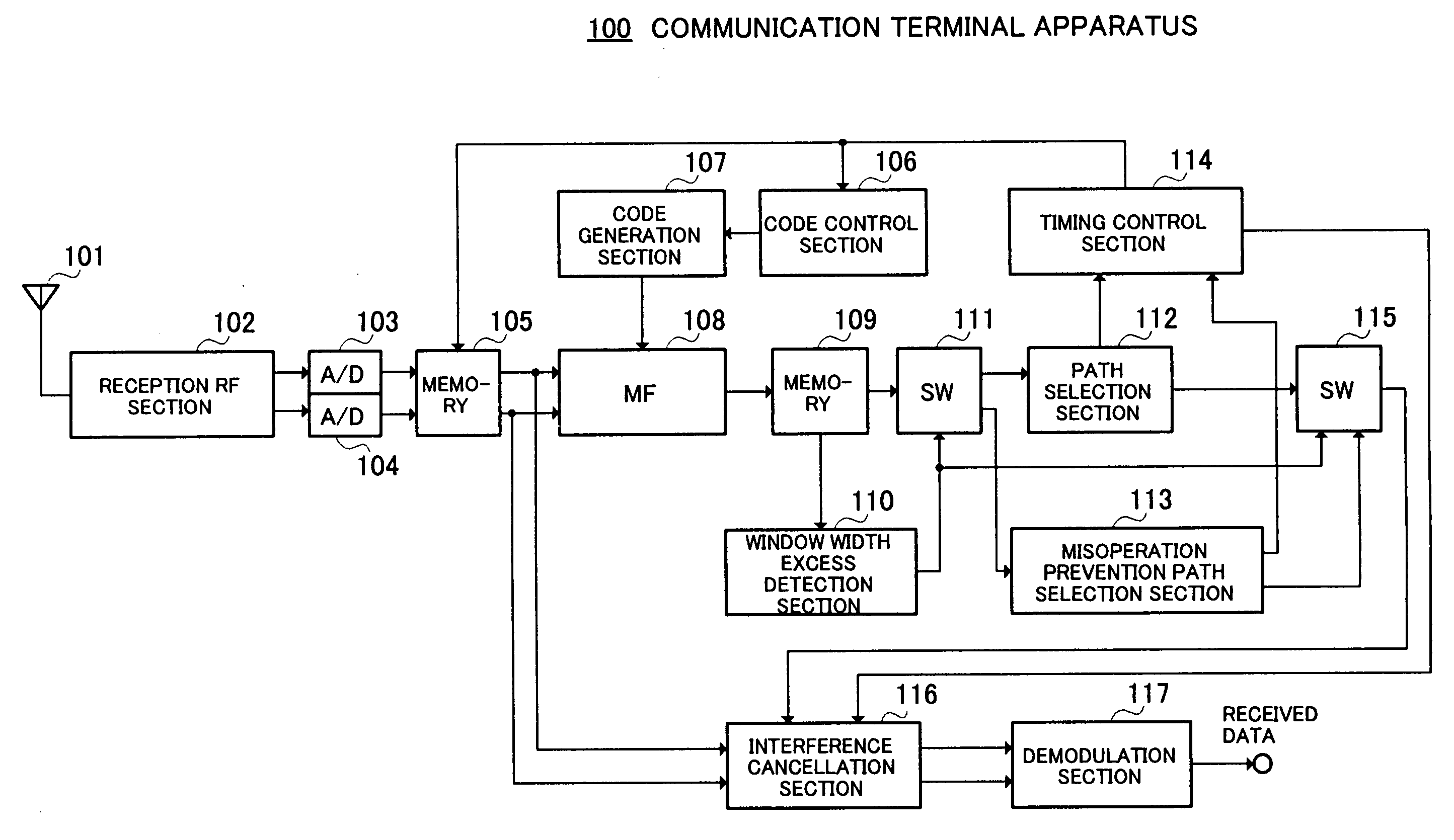
[0082] FIG. 6 illustrates a configuration of a communication terminal apparatus according to A communication terminal apparatus 100 inputs a signal received by an antenna 101 to a reception RF section 102. The reception RF section 102 performs reception processing including frequency conversion, etc., on the received signal to generate Ich baseband signal (in-phase component) and Qch baseband signal (quadrature component).

[0083] An A / D converter 103 (104) performs an A / D conversion on the Ich (Qch) baseband signal to generate an Ich (Qch) digital baseband signal. A memory 105 stores the generated Ich and Qch digital baseband signals and outputs the stored digital baseband signals to a matched filter (MF) 108 and interference cancellation section 116 as delay profile generation sections based on a control signal from a timing control section 114.

[0084] The MF 108 finds a correlation between a code generated by a code generation section 107 and the received signal and generates a del...

embodiment 2

[0115] Above described Embodiment 1 has described the case where when delay spreading .tau..sub.k exceeds the detection window width W.sub.N, the part that exceeds the detection window W.sub.N (section 0 to .alpha.+.DELTA.t) is masked to 0 and paths are not selected in this part. However, this embodiment proposes a communication terminal apparatus which can select paths in this part.

[0116] That is, the present inventor et al. have considered that unconditionally masking the part that exceeds the detection window W.sub.N (section 0 to .alpha.+.DELTA.t) reduces a path diversity effect when as shown in, for example, FIG. 12B, paths of the communication terminal user #2 are included in the section 0 to .alpha.+.DELTA.t and the signal quality after interference cancellation would deteriorate accordingly compared to the case where all paths are exactly detected. Thus, instead of unconditionally masking the section 0 to .alpha.+.DELTA.t to 0 as in the case of Embodiment 1, this embodiment ...

embodiment 3

[0133] Above described Embodiment 1 has described the case as shown in FIG. 5A where when delay spreading .tau..sub.k detected at the time slot TS#0 exceeds the detection window width W.sub.N, the part which exceeds the detection window is masked to 0 to thereby avoid path selection in this part, but this embodiment proposes a communication terminal apparatus which does not avoid path selection unconditionally for the section (0 to .alpha.+.DELTA.t) which exceeds the detection window but applies, as shown in FIG. 15B, no mask processing to the section (0 to .alpha.+.DELTA.t) when midamble codes to be detected in the adjacent window are not assigned and selects no paths for the section (0 to .alpha.+.DELTA.t) which exceeds the detection window when midamble codes to be detected within the adjacent detection window are assigned.

[0134] That is, when delay spreading .tau..sub.k which exceeds the window width W.sub.N of the detection window is detected at the time slot TS#0, Embodiment 1...


PUM


Abstract

The radio reception section 1102 receives a received signal whose band has been restricted using a filter. The delay profile creation section 1104 creates continuous delay profiles for every midamble shift. The distortion component creation section 1106 creates start path distortion components by multiplying the power value of the start sample of each midamble shift by a coefficient of the filter. The removing section 1107 removes the start path distortion components of the following midamble shift from predetermined samples behind the delay profile of each midamble shift. The path selection section 1108 selects samples whose power value is equal to or greater than a threshold as paths from the delay profile with the start path distortion components removed as paths.

Description

[0001] The present invention is applicable to reception processing compliant with standards for next-generation cellular phones adopted in China such as a TD-SCDMA scheme or TD-CDMA scheme (both are schemes also called "CDMA-TDD schemes").[0002] In a digital mobile communication system, a received signal includes not only signals for the own station but also signals for other stations which are superimposed as interference components, and therefore it is necessary to remove these interference components. For this reason, a communication terminal apparatus is generally provided with an interference cancellation apparatus.[0003] FIG. 1 shows a schematic view of a mobile communication system using a communication terminal apparatus provided with an interference cancellation apparatus. In a conventional mobile communication system shown in FIG. 1, a base station BS performs radio communications with K communication terminals (FIG. 1 shows only communication terminal U-1 and communicatio...

Claims


Application Information

Patent Timeline
Patent Type & Authority Applications(United States)
IPC IPC(8): H04B1/707H04L25/02
CPCH04B1/70754H04B1/7103H04B1/71052H04B1/7113H04B1/7117H04B2201/709709H04L25/0212H04L25/0228
Inventor TAKAHASHI, HIDEYUKIHIRAMATSU, KATSUHIKOSETO, YOSHITAKANAKA, KATSUYOSHI
Owner PANASONIC CORP
Why Eureka
Try Eureka