System and method for ray tracing using reception surfaces

a technology of ray tracing and reception surfaces, applied in the direction of antenna supports/mountings, electrical equipment, network planning, etc., can solve the problems of insufficient coverage, pbx (private branch exchange) system or wireless local area network (wlan) can be rendered useless, and the cost of in-building and microcell devices providing wireless coverage is diminishing

Inactive Publication Date: 2004-12-23
WIRELESS VALLEY COMM
View PDF99 Cites 176 Cited by
  • Summary
  • Abstract
  • Description
  • Claims
  • Application Information

AI Technical Summary

Benefits of technology

[0032] As in-building wireless LANs and microcell wireless systems proliferate, all of the issues facing network installers, carriers, network technicians, and end users may now be resolved quickly, easily, and inexpensively using the current invention. The current invention allows popular site-specific design, deployment, and real time network management products, such as those offered by Wireless Valley, to predict network performance using a more efficient ray-tracing approach based on the concept of reception surfaces.
[0033] As in-building wireless LANS, WiMax, and last-mile broadband wireless networks using MiMO and Mesh networking, as well as in-building UWB wireless networks proliferate, network performance and position location issues facing network installers, carriers, technicians, and end-users, and eventually autonomous network controllers, will be resolved quickly, easily, and inexpensively using the current invention. In addition to more efficient computation and computer representation in the ray tracing process, the current invention also displays predicted or measured network performance in an easily interpretable manner.
[0036] To accomplish the above, a 2-D or 3-D site-specific model of the physical environment is stored as a CAD model in an electronic database. This model may be extensive and elaborate with great detail, or it may be extremely simple to allow low cost and extreme ease of use by non-technical persons wanting to view the physical layout of the network. The physical, electrical, and aesthetic parameters attributed to the various parts of the environment such as walls, ceilings, doors, windows, floors, foliage, buildings, hills, and other obstacles that affect radio waves or which impede or dictate the routing of wiring paths and other wired components may also stored in the database, such as performed using Wireless Valley SitePlanner or LANPlanner products. A representation of the environment is displayed on a computer screen for the designer to view. Note that the network / computer controller may display the screen remotely on a device different than where the computing and ray-tracing prediction is performed (e.g. through Internet web browsing or dedicated video channels), or may display the screen on a monitor which is part of the computer controller which implements the reception surface ray tracing prediction engine and other processing for network control signals. Furthermore, the computer controller may be distributed among different sites or computer platforms, either in the network or distributed between clients and servers, or co-located or located remotely from the actual network of interest. The designer may view the entire environment in simulated 3-D, zoom in on a particular area of interest, or dynamically alter the viewing location and perspective to create a "fly-through" effect.
[0039] Through novel processing techniques provided by the present invention, the RF performance of any wireless network of equipment can be predicted. Radio waves transmitted from any source represented within the wireless network--or attached to any device interacting or interfering with the wireless network--are predicted to propagate through the site-specific model of the environment. Reception surfaces--virtual obstructions inserted into the site-specific environmental model that act as collection surfaces for radio wave data--are positioned, either automatically under computer control, or manually by the user, throughout the site-specific environmental model. As radio waves (rays) are predicted to move through the site-specific model and as they encounter these reception surfaces, all characteristics of the radio wave at the point in space at which the encounter with the reception surface occurs is recorded in memory. By later analyzing the reception surfaces, the RF channel environment at the point within the site-specific model of the environment bounded by or in close location to the reception surface can be accurately determined.

Problems solved by technology

As data communications use increases, radio frequency (RF) coverage within and around buildings and signal penetration into buildings from outside transmitting sources has quickly become an important design issue for network engineers who must design and deploy cellular telephone systems, paging systems, wireless or wired computer networks, or new wireless systems and technologies such as personal communication networks, wireless local area networks (WLANs), ultrawideband networks, RF ID networks, and WiFi / WiMax last-mile wireless networks.
A common problem for wireless networks is inadequate coverage, or a "dead zone" in a specific location, such as a conference room.
Such dead zones may actually be due to interference, rather than lack of desired signal.
It is understood that an indoor Voice over IP (VOIP) wireless PBX (private branch exchange) system or wireless local area network (WLAN) can be rendered useless by interference from nearby, similar systems, or by lack of coverage or throughput in desired locations.
The costs of in-building and microcell devices which provide wireless coverage are diminishing, and the workload for RF engineers and technicians to install and manage these on-premises systems is increasing sharply.
In many cases, the wireless network interferes with itself, forcing the designer to carefully analyze many different equipment configurations in order to achieve proper performance.
Information of that type would otherwise only be available through complex and often exhausting measurement collection.
However, even with advances in computing capabilities, use of ray tracing models is not yet widespread among wireless engineers.
This is due, in part, to various problems that continue to make ray-tracing models impractical.
First, ray tracing is computationally intensive even by the computing standards of today.
Secondly, there is a decided lack of highly detailed, readily available site-specific information of sufficient resolution for ray tracing models to be applied optimally.
Third, there are no efficient techniques for calibrating ray tracing algorithms given measurement information; therefore, if the results of the ray-tracing algorithm do not closely match the measured data, a wireless designer has little to assist in adjusting the parameters of the algorithm to compensate.
Instead, these sources utilize alternative, less efficient predictive techniques.
PLAnet also provides facilities for optimizing the channel settings of wireless transceivers within the environment, but does not provide for further adaptive transceiver configurations beyond channel settings.
Further, they do not use reception surfaces in a ray tracing engine.
nts. None of these methods use reception surfaces with a ray tracing en
None of the aforementioned design tools none contemplate the use of reception surfaces for ray tracing methods as part of their prediction method.

Method used


Image

  • System and method for ray tracing using reception surfaces
  • System and method for ray tracing using reception surfaces
  • System and method for ray tracing using reception surfaces

Examples


Embodiment Construction

[0050] The design of communication systems is often a very complex and arduous task, with a considerable amount of effort required to simply analyze the results of system performance. Using the present method, it is now possible to improve the accuracy and efficiency of the prediction of communication system performance. The present invention is a significant advance over the prior art through its use of a novel method of capturing and analyzing predicted radio wave propagation data in a ray tracing engine.

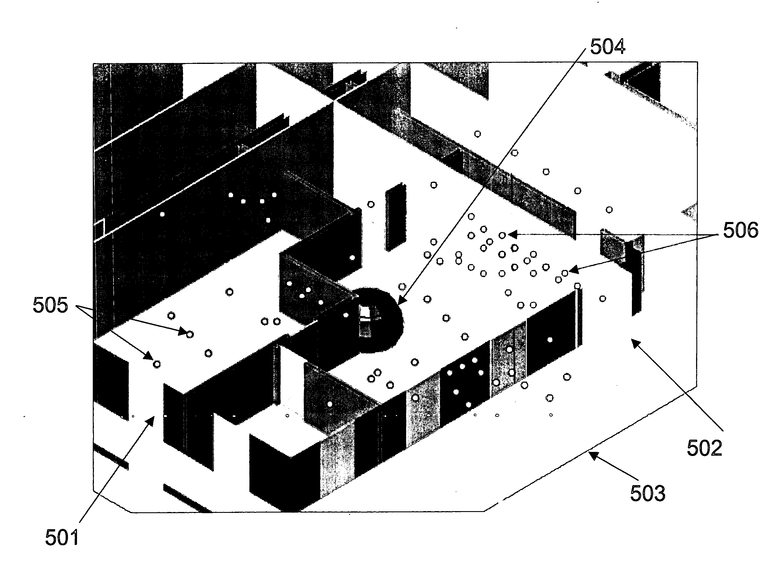
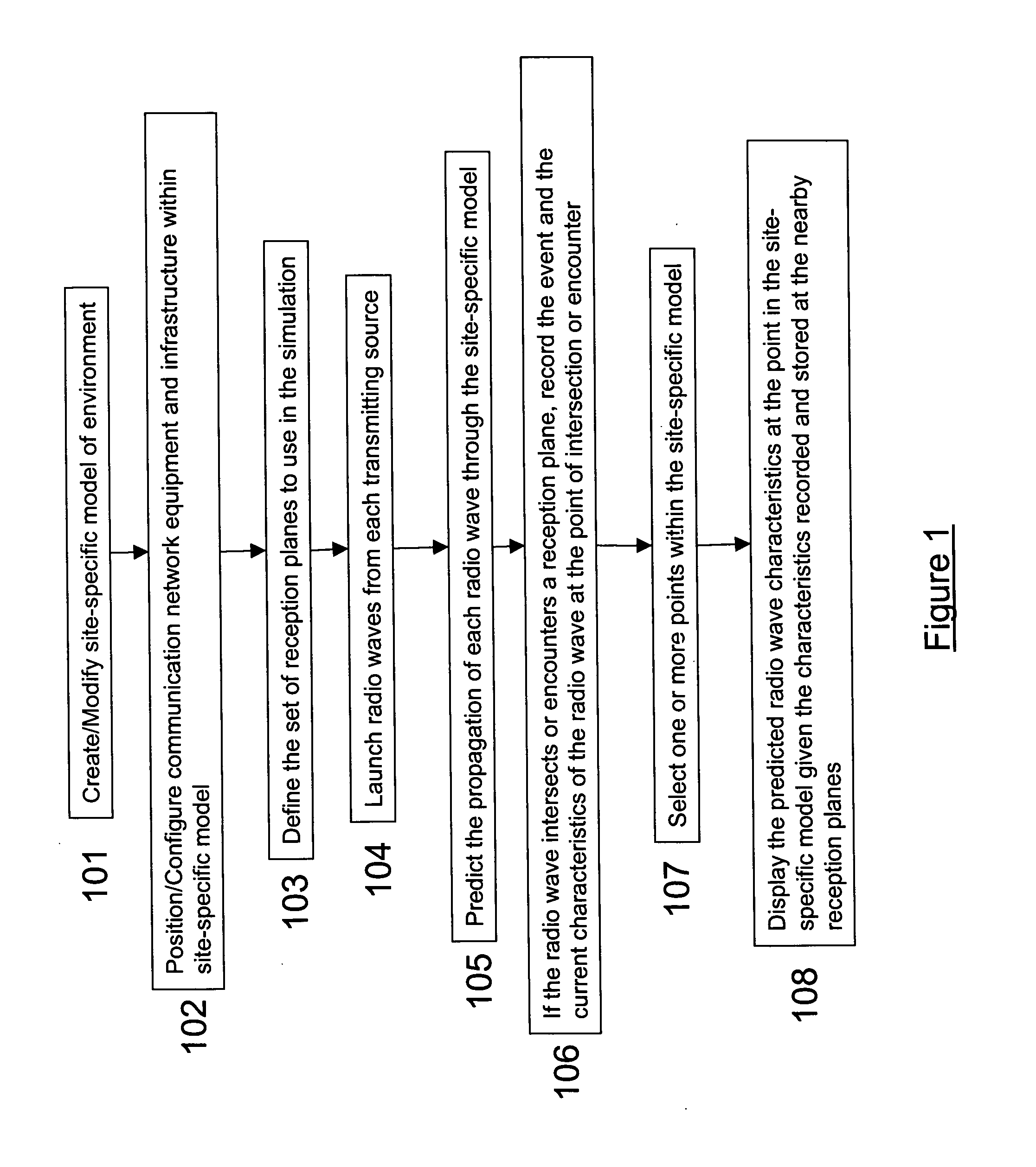
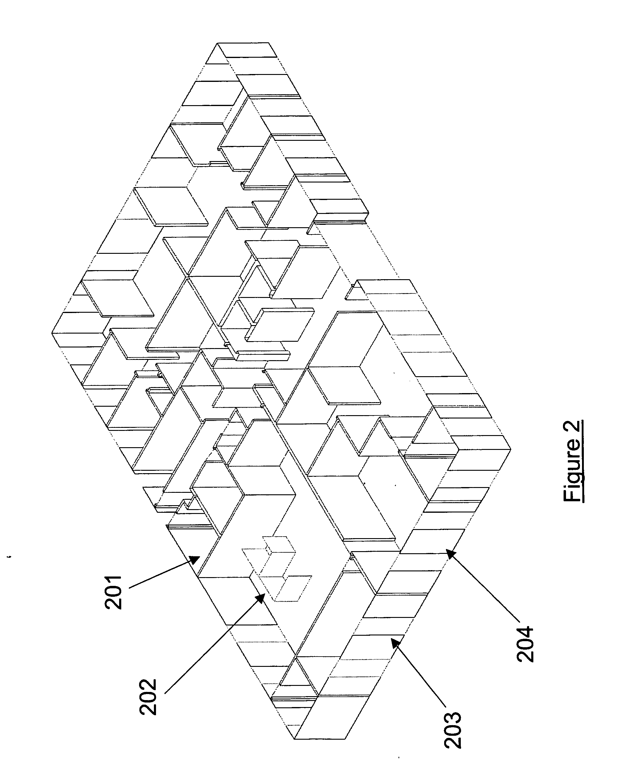
[0051] Referring now to FIG. 1, there is shown the general process of the present method. In order to begin analyzing a communication network, a site-specific computer representation of the environment in which the communication network is or will be deployed is created 101. The present invention uses 2-D or 3-D computer aided design (CAD) renditions of a part of a building, a building, or a collection of buildings and / or surrounding terrain and foliage. However, any information r...


PUM


Abstract

This invention provides a system and method for efficient ray tracing propagation prediction and analysis. Given a site-specific model of a physical environment, the present invention places virtual obstructions known as reception surfaces within the environment. As radio waves are predicted to propagate through the environment and intersect with or encounter reception surfaces, the characteristics of the radio wave are captured and stored relative to the location of the interaction with the reception surface. The radio frequency channel environment at any point within the site-specific model can be derived through analysis of the radio wave characteristics captured at nearby reception surfaces.

Description

[0001] This application claims priority and stems from provisional patent application No. 60 / 464,660 filed on Apr. 23, 2003, entitled "A Comprehensive Method and System for the Design and Deployment of Wireless Data Networks." The disclosed invention is also related to U.S. Pat. No., 6,317,599, U.S. Pat. No. 6,442,507, U.S. Pat. No. 6,493,679, U.S. Pat. No. 6,499,006, U.S. Pat. No. 6,625,454, and U.S. Pat. No. 6,721,769; and the complete contents of these patents are herein incorporated by reference.[0002] 1. Field of the Invention[0003] The present invention generally relates to radio wave propagation and the radio frequency (RF) design and prediction of wireless communication networks, and more particularly, to a site-specific ray-tracing method for determining the RF channel characteristics at any given position in a physical environment given wireless communication equipment transmitting within the physical environment.[0004] 2. Background Description[0005] As data communication...

Claims


Application Information

Patent Timeline
Patent Type & Authority Applications(United States)
IPC IPC(8): H01Q1/24H04W16/18H04W16/20
CPCH04W16/18H04W16/20
Inventor RAPPAPORT, THEODORE S.SKIDMORE, ROGER R.
Owner WIRELESS VALLEY COMM
Why Eureka
Try Eureka