Method of forming sputtering target assembly and assemblies made therefrom

a technology of sputtering target and assembly, which is applied in the direction of electrolysis components, vacuum evaporation coatings, coatings, etc., can solve the problems of individual bonding of a target and a backing plate, time-consuming and resource-intensive, and quality control

Inactive Publication Date: 2004-12-30
CABOT CORP
View PDF38 Cites 43 Cited by
  • Summary
  • Abstract
  • Description
  • Claims
  • Application Information

AI Technical Summary

Benefits of technology

0007] It is therefore a feature of the present invention to provide an improved...

Problems solved by technology

A common disadvantage of conventional bonding techniques is the individual bonding of a target and a backing plate, i.e., sputtering target assemblies are formed one at a time.
First, it can be quite time-consuming and resource intensive, owing to the batch nature of production and inherent costs of the bonding process.
Another drawback concerns quality control.
However, variables in the bonding process affecting bond integrity can lead to uncertainty as to the relatedness of the bond quality of one sputtering target assembly to that of another.
Moreover, sacrificing a certain percentage of otherwise usable sputtering target assemblies for quality control purposes adds to the overall cost of sputtering target assembly production.
Another disadvantage of conventional bonding techniques is that they are feasible only for a sputte...

Method used


Image

  • Method of forming sputtering target assembly and assemblies made therefrom
  • Method of forming sputtering target assembly and assemblies made therefrom
  • Method of forming sputtering target assembly and assemblies made therefrom

Examples


Embodiment Construction

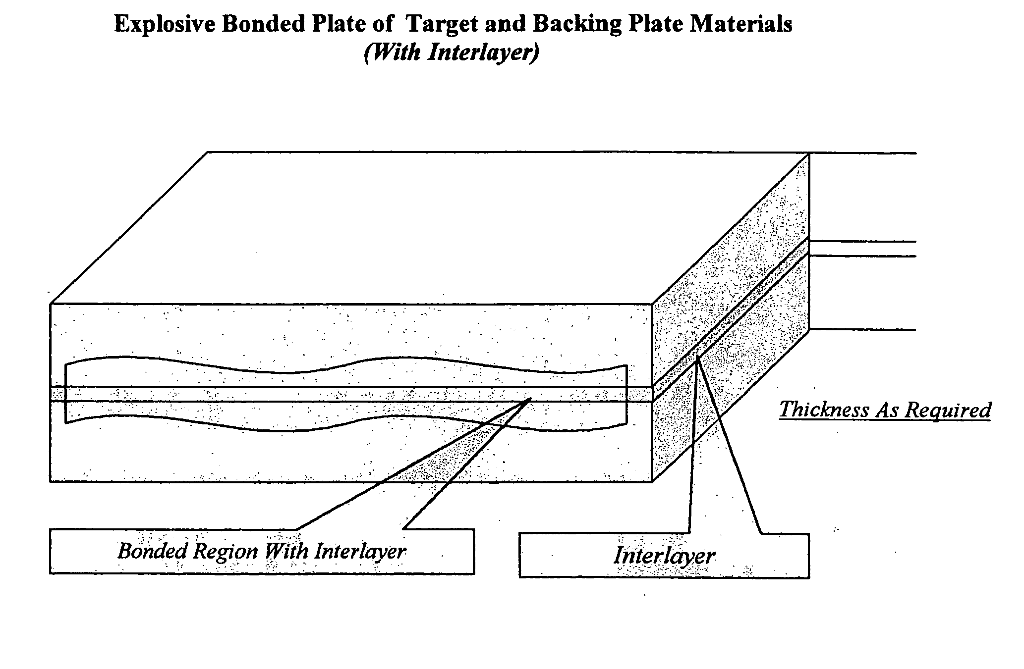
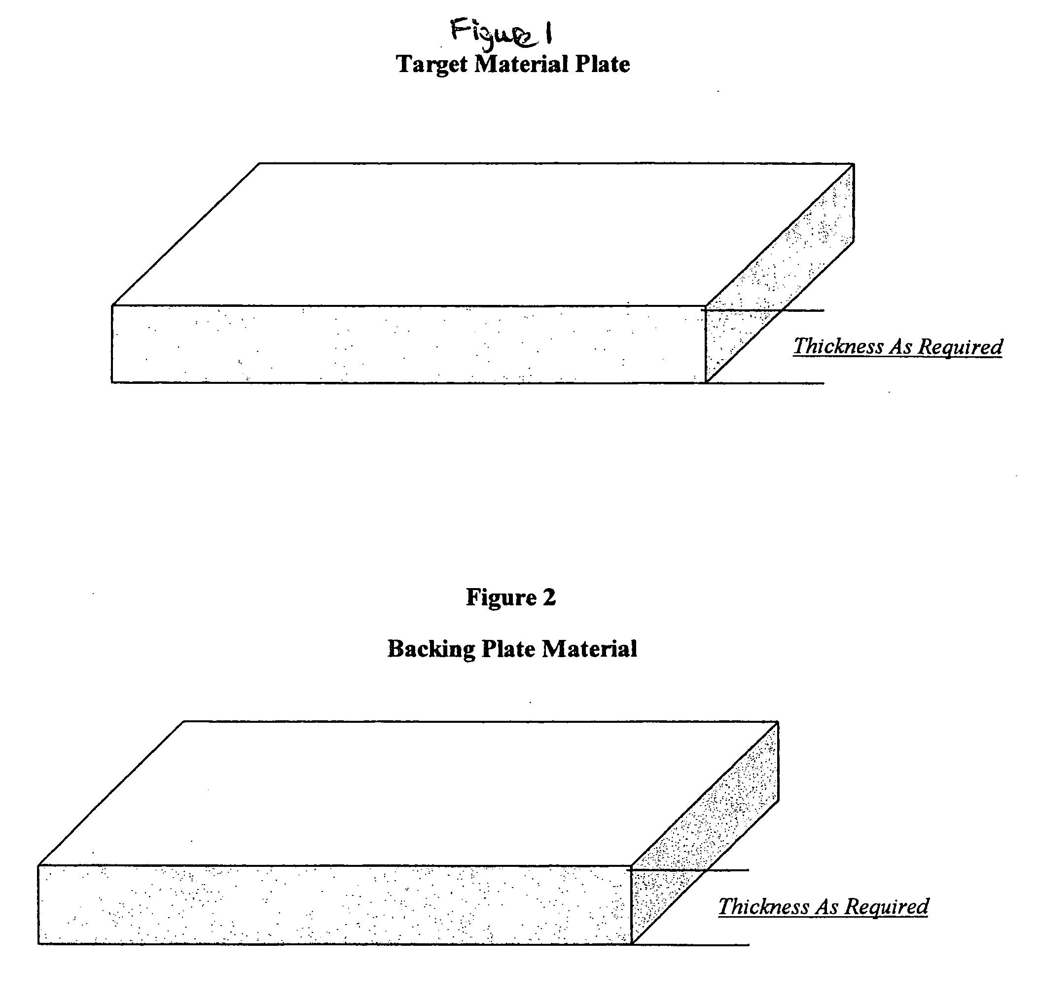
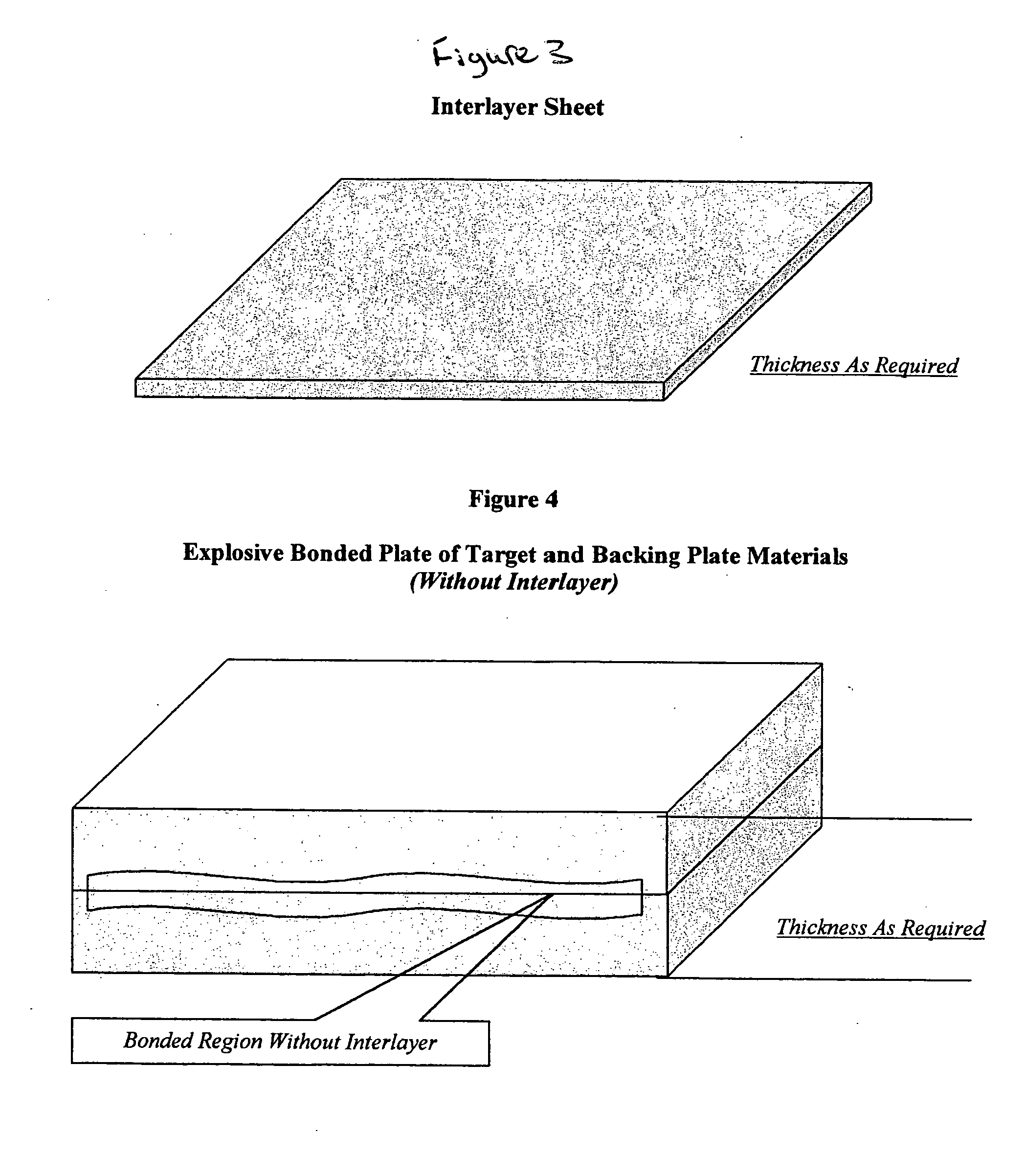
[0028] A method according to the present invention for forming a sputtering target assembly involves explosively bonding a target grade plate and a backing plate member to form a bonded preform, and optionally partitioning the bonded preform to form a plurality of sputtering target assemblies. An interlayer can optionally be disposed between the target grade plate and the backing plate member before bonding. The present invention further relates to forming a large target which is bonded onto a backing plate. This bonded target is larger than conventional target sizes and can be useful in applications where a series or mosaic of targets are needed to form a large sputter surface area.

[0029] In more detail, the preform that is optionally divided into multiple target assemblies preferably includes two components, namely, a backing plate member having a bonding surface and a sputter target grade plate or target grade plate having a bonding surface and having a sputter surface. The backi...


PUM

PropertyMeasurementUnit
Grain sizeaaaaaaaaaa
Lengthaaaaaaaaaa
Lengthaaaaaaaaaa

Abstract

A method of forming a sputtering target assembly is described that involves explosively bonding a target grade plate and a backing plate member to form a bonded preform having dimensions such that a large target or several target assemblies can be obtained. The method includes optionally partitioning the bonded preform into a plurality of sputtering target assemblies. An interlayer can optionally be disposed between the target grade plate and the backing plate member before bonding. A bond quality test sample can be produced by the method. The sputtering target assemblies, the bonded preform, and the bond quality test sample are further described.

Description

[0001] This application claims the benefit under 35 U.S.C. .sctn.119(e) of prior U.S. Provisional Patent Application No. 60 / 450,196 filed Feb. 25, 2003, which is incorporated in its entirety by reference herein.[0002] The present invention relates to a method of forming a sputtering target assembly. More specifically, the method includes the preferred use of explosion bonding to form a sputtering target assembly.[0003] Numerous bonding techniques are used to bond sputtering target assembly components (e.g., a sputter target or target blank and a backing plate) together, such as soldering, brazing, diffusion bonding, mechanical fastening, epoxy bonding, friction welding, explosion bonding, etc. Each of the bonding techniques has its own advantages and disadvantages. A common disadvantage of conventional bonding techniques is the individual bonding of a target and a backing plate, i.e., sputtering target assemblies are formed one at a time. Singularly forming sputtering target assembl...

Claims


Application Information

Patent Timeline
IPC IPC(8): C23C14/34
CPCC23C14/3407
Inventor FORD, ROBERT B.MICHALUK, CHRISTOPHER A.WICKERSHAM, CHARLES E. JR.
Owner CABOT CORP
Why Eureka
Try Eureka