Optical pickup apparatus, condensing optical system, and optical element

a pickup apparatus and optical element technology, applied in the field of optical pickup apparatus, condensing optical system, optical element, can solve the problems of difficult to perform temperature characteristic correction of correction of wave aberration of optical element, difficult to satisfy the sine condition of off-axis coma correction while correcting spherical, and difficult to perform chromatic aberration correction of optical element chromatic aberration,

Inactive Publication Date: 2004-12-30
KONICA MINOLTA OPTO
View PDF3 Cites 12 Cited by
  • Summary
  • Abstract
  • Description
  • Claims
  • Application Information

AI Technical Summary

Problems solved by technology

In general, in an optical pickup apparatus having compatibility, since the respective types of optical information recording media (e.g., a DVD and CD) vary in protective substrate thickness and the wavelength of a light beam to be used, it is difficult to satisfy the sine condition for correcting off-axis coma while correcting spherical aberration and wave aberration for both a DVD and a CD.
In addition, it is difficult to perform "temperature characteristic correction" of correcting a change in the wave aberration of an optical element with a temperature change for the respective types of optical information recording media.
Since the wave aberration worsens as the focus position of a condensed light spot deviates due

Method used


Image

  • Optical pickup apparatus, condensing optical system, and optical element
  • Optical pickup apparatus, condensing optical system, and optical element
  • Optical pickup apparatus, condensing optical system, and optical element

Examples


first embodiment

[0168] Tables 1 and 2 show the lens data of the optical element and objective lens used in the

1TABLE 1 focal length: f.sub.1 = 2.75 mm, f.sub.2 = 2.82 mm numerical aperture: NA1 = 0.65, NA2 = 0.63 imaging magnification: m = 0.0, m = 0.0 i.sup.th Di Ni Di Ni Surface Ri (405 nm) (405 nm) (660 nm) (660 nm) 0 .infin. .infin. 1 .infin. 0.0 1.0 0.0 1.0 stop diameter: 3.575 mm 2 1.74038 1.7000 1.542936 1.7000 1.528968 aspherical surface / diffraction surface 3 -6.89562 1.33286 1.0 1.38663 1.0 aspherical surface / diffraction surface 4 .infin. 0.6 1.614341 0.6 1.577181 5 .infin.

[0169] As shown in Table 1, the objective lens according to the first embodiment is designed such that when a light beam emitted from the first light source has the wavelength .lambda.1 (=405 nm), focal length f.sub.1=2.75 mm, image-side numerical aperture NA1=0.65, and imaging magnification m=0.0 are set, whereas when a light beam emitted from the second light source has the second wavelength .lambda.2 (=660 nm), focal ...

second embodiment

[0176] The second embodiment of the optical pickup apparatus, condensing optical system, and optical element of the present invention will be described next.

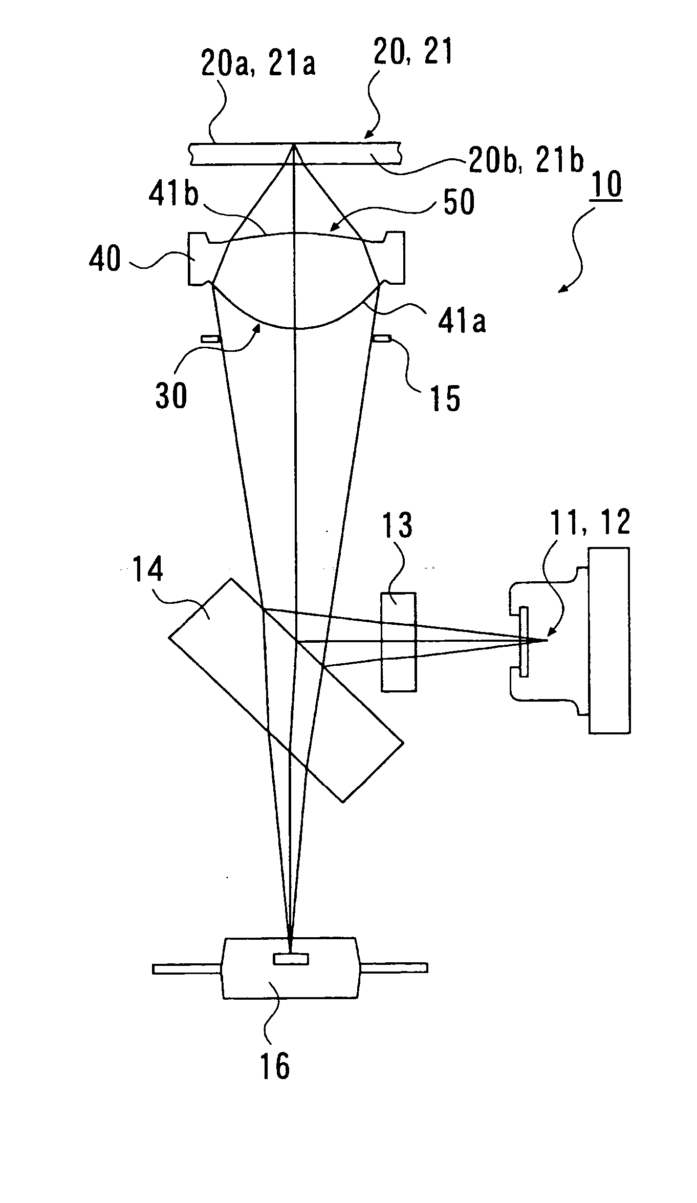
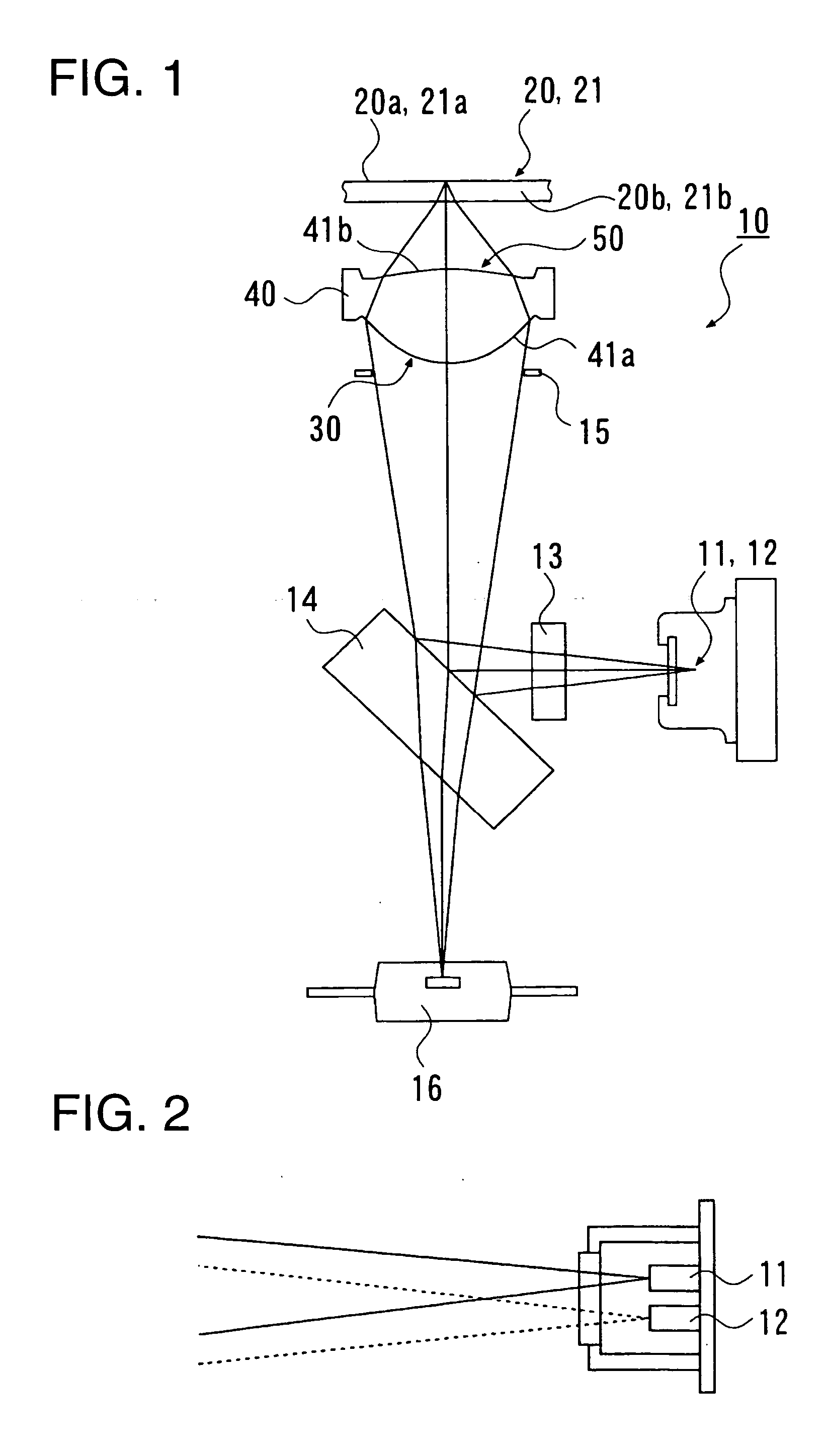
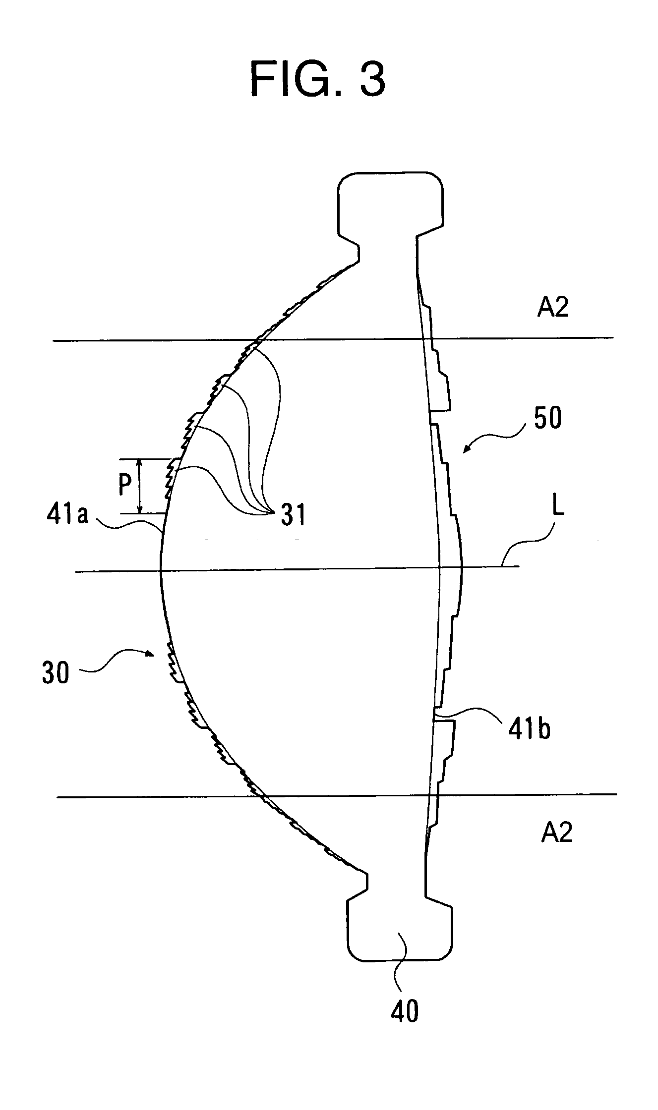
[0177] The optical pickup apparatus of the second embodiment has compatibility with DVDs and CDs. An objective lens 40 used in the second embodiment is a single lens with two aspherical surfaces. A first phase modulator is provided in a central area A1, formed on the incident surface of the objective lens, whose height h from an optical axis L is 1.555 mm or less, and a second phase modulator is provided in a central area, formed on the exit surface, whose height h from the optical axis L is 1.24 mm or less. The optical pickup apparatus using this objective lens has an arrangement like that shown in FIG. 1, in which two types of divergent light beams of different wavelengths are incident on the objective lens 40. Note that in this embodiment, staircase-like discontinuous parts are also formed in a peripheral area A2 of the incid...

third embodiment

[0187] The third embodiment of the optical pickup apparatus, condensing optical system, and optical element of the embodiment of the present invention will be described next.

[0188] The third embodiment exemplifies an optical pickup apparatus including an optical element which reduces the occurrence of aberration at the time of a change in temperature and having compatibility with DVDs and CDs.

[0189] As shown in FIG. 11, an optical element 70 in the form of a parallel plate (a correction element for reducing the occurrence of aberration accompanying a change in ambient temperature) is provided near an objective lens 40 as a single lens with two aspherical surfaces, and a light beam from a light source is incident as parallel light on the objective lens 40. A first phase modulator 30 is provided on the incident surface (the surface on the light source side) of the optical element 70, and a second phase modulator 50 is provided on the exit surface (the surface on the optical informatio...


PUM


Abstract

This invention is directed to an optical pickup apparatus, condensing optical system, and optical element which can at least reproduce and/or record information from/on a first optical information recording medium having a protective substrate thickness t1 by using a light beam of a first wavelength lambda1 emitted from a first light source, and reproduce and/or record information from/on a second optical information recording medium having a protective substrate thickness t2 (t2>=t1) by using a light beam of a second wavelength lambda2 (lambda2>lambda1) emitted from a second light source. The optical pickup apparatus of the invention includes a first phase modulator which gives a diffraction effect to only the light beam of the wavelength lambda1 on at least one optical surface, of a plurality of optical surfaces of a plurality of optical elements arranged on a common optical path through which the light beam of the first wavelength lambda1 and the light beam of the second wavelength lambda2 pass, and a second phase modulator which gives a diffraction effect to only the light beam of the wavelength lambda2 on at least one of the remaining optical surfaces. Each of the first phase modulator and second phase modulator has staircase-like discontinuous parts, each formed from a predetermined number of stepped portions, formed concentrically around an optical axis at the pitch defined by an optical path difference function.

Description

[0001] 1. Field of the Invention[0002] The present invention relates to an optical pickup apparatus, condensing optical system, and optical element which condense a light beam onto the information recording surface of an optical information recording medium.[0003] 2. Description of the Prior Art[0004] Recently, as short-wavelength red lasers have been put into practice, DVDs (Digital Versatile Disks) have been commercially available, which are high-density optical information recording media (also called optical disks) almost equal in size to CDs (Compact Disks) and having large capacities.[0005] In addition to the above CDs and DVDs, optical disks with various specifications which differ in light source wavelength and protective substrate thickness have been commercialized, including a CD-R and RW (rewritable compact disks), VD (Video Disk), MD (Mini Disk), MO (Magneto Optical disk), and the like.[0006] As the wavelengths of semiconductor lasers become shorter, research and develop...

Claims


Application Information

Patent Timeline
IPC IPC(8): G11B7/00G11B7/125G11B7/135
CPCG11B7/1275G11B7/1353G11B7/1374G11B2007/0006
Inventor MIMORI, MITSURU
Owner KONICA MINOLTA OPTO
Why Eureka
Try Eureka