Microfluidic chromatography

a technology of microfluidic chromatography and chromatography chamber, which is applied in the direction of separation processes, instruments, transportation and packaging, etc., can solve the problems of limited application of otlc and pclc techniques, inapplicability of conventional separation techniques, and insufficient compliance of conventional sample pumping systems

Inactive Publication Date: 2005-01-06
FLUIDIGM CORP
View PDF74 Cites 127 Cited by
  • Summary
  • Abstract
  • Description
  • Claims
  • Application Information

AI Technical Summary

Benefits of technology

[0040] In one embodiment of the present invention, the flow channel is located on an interface between a solid substrate and the elastomeric polymer such that an inner surface of the flow channel comprises an elastomeric polymer portion and a solid substrate portion. In one particular embodiment, the stationary phase is attached to the solid substrate portion of the flow channel inner surface. In one specific embodiment, the elastomeric polymer portion of the flow channel inner surface comprises a surface coating that reduces a non-specific binding of the analyte.

Problems solved by technology

However, due to the small sample size (e.g., nanoliter to microliter) used by these microfluidic devices, conventional separation techniques are not applicable.
Unfortunately, in order to achieve the desired sensitivity and efficiency in OTLC and PCLC, the inner diameter of OTLC and PCLC columns need to be small, generally in the order of 50 μm or less, and preferably about 10 μm or less.
Conventional sample pumping system can not adequately meet this stringent requirement.
In addition, difficulties with large interconnection dead volume and detection volume between the OTLC or PCLC column and the fluid delivery (i.e., pumping) system have greatly limited the application of OTLC and PCLC techniques.

Method used


Image

  • Microfluidic chromatography
  • Microfluidic chromatography
  • Microfluidic chromatography

Examples


Embodiment Construction

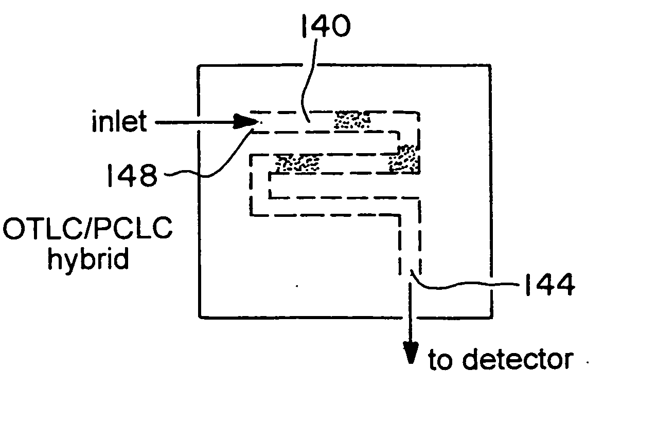
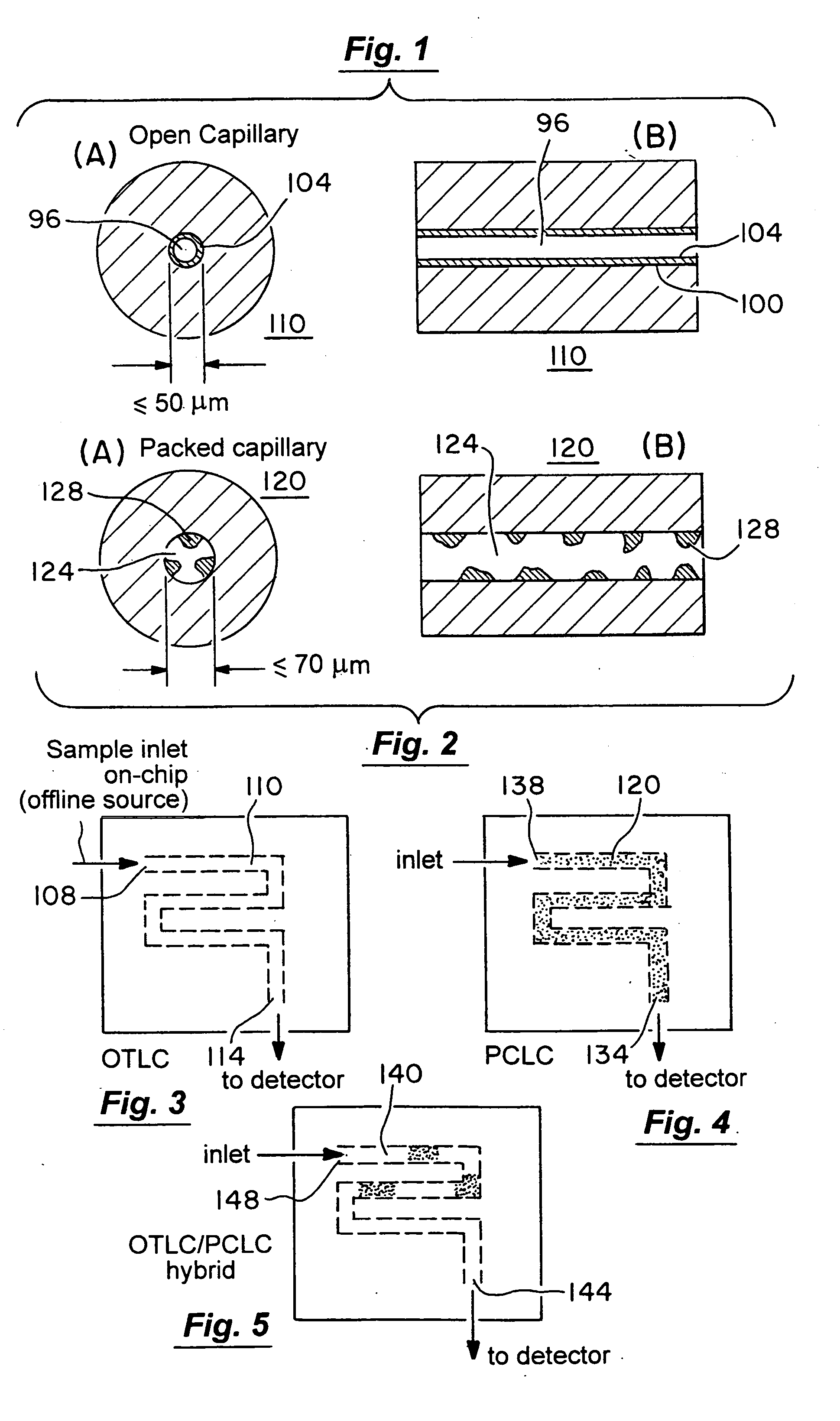
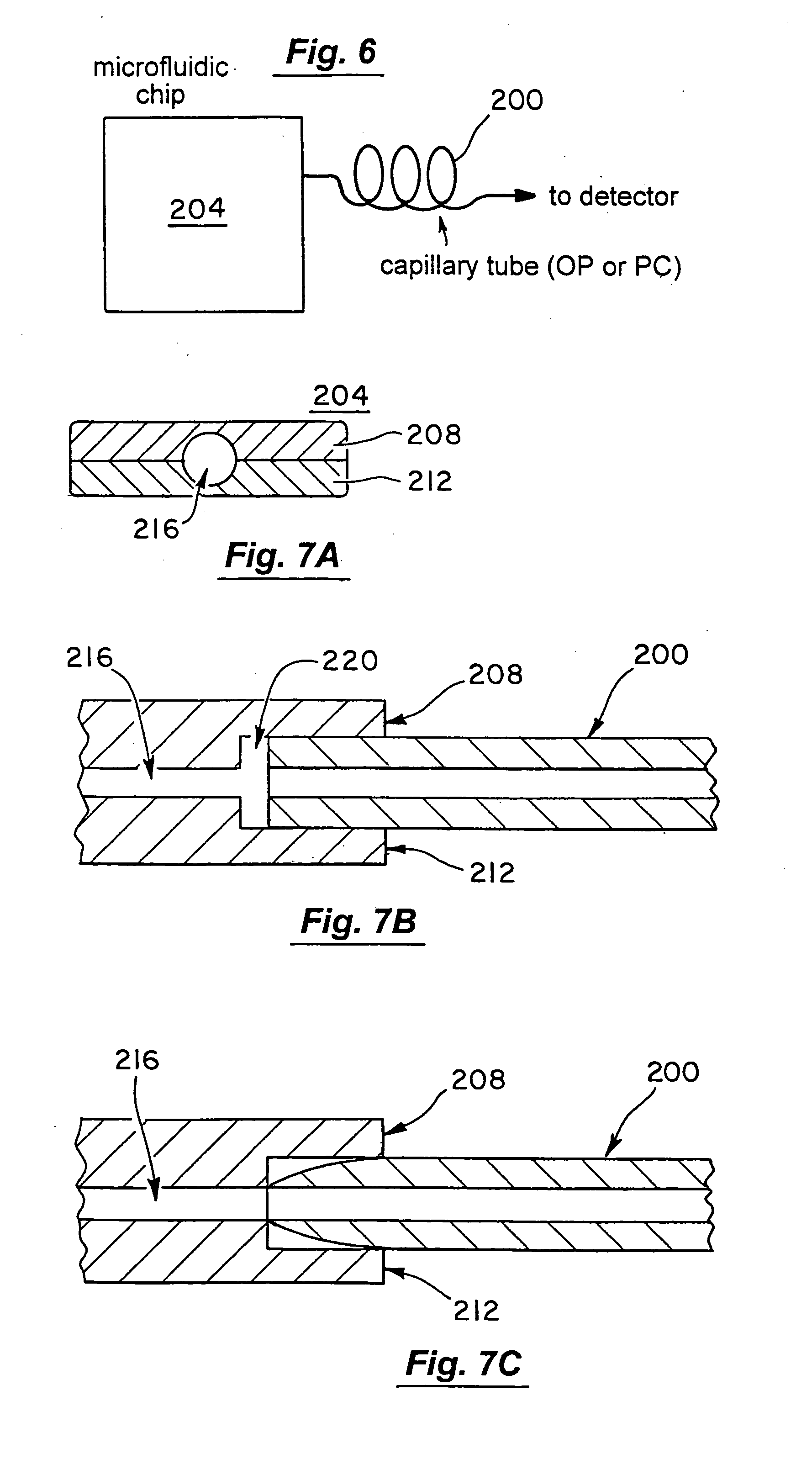
[0120] One aspect of the present invention provides a microfluidic chromatography apparatus, a method for producing the same, and a method for using the same. Preferably, the microfluidic chromatography apparatus of the present invention comprises a microfabricated fluid delivery system and a chromatography column, preferably an OTLC column, PCLC column, or combinations thereof. The chromatography column can be an integral part of the microfabricated fluid delivery system and as such it can be microfabricated within the microfabricated fluid delivery system. Preferably, the chromatography column can be fabricated separately and integrated into the microfabricated fluid delivery system. The microfabricated fluid delivery system of the present invention is capable of delivering the fluid at a flow rate of 100 μL / min or less, preferably 10 μL / min or less, and more preferably 1 μL / min or less.

[0121] The microfabricated fluid delivery system of the present invention is produced from a p...


PUM

PropertyMeasurementUnit
pressureaaaaaaaaaa
pressureaaaaaaaaaa
inner diameteraaaaaaaaaa

Abstract

The present invention is directed to a microfluidic chromatography apparatus comprising a microfabricated fluid delivery system and a chromatography column which is in fluid communication with the fluid delivery system, and a method for producing and using the same. Preferably, the chromatography column comprises an OTLC, PCLC, or combinations thereof.

Description

CROSS-REFERENCES TO RELATED APPLICATIONS [0001] This application claims the benefit of U.S. Provisional Patent Application Ser. No. 60 / 281,937, filed Apr. 6, 2001.FIELD OF THE INVENTION [0002] The present invention relates to a microfluidic device comprising a microfabricated fluid delivery system and a chromatography column. In particular, the present invention relates to a microfluidic device comprising an OTLC column, PCLC column, or combinations thereof, which is operatively interconnected to a microfabricated fluid delivery system. BACKGROUND OF THE INVENTION [0003] Microfluidic devices allow manipulation of extremely small volumes of liquids, and therefore are particularly useful in small scale sample preparations, chemical synthesis, sample assay, sample screening, and other applications where a micro-scale amount of samples are involved. For many applications, the chemical make up of the resulting material (i.e., sample) needs to be analyzed. Such analysis typically requires...

Claims


Application Information

Patent Timeline
Patent Type & Authority Applications(United States)
IPC IPC(8): G01N30/38G01N30/52G01N30/60
CPCG01N30/6065G01N30/6095Y10T436/2575G01N2030/521G01N2030/387Y10T137/86863B01D15/08
Inventor HUANG, JIANGCHOU, HOU-PUUNGER, MARC A.
Owner FLUIDIGM CORP
Why Eureka
Try Eureka