
Photonic colloidal crystal columns and their inverse structures for chromatography

a colloidal crystal and chromatographic technology, applied in the field of chromatographic apparatuses, can solve the problems of non-linear change, limited detection of rapid changes of solvent or mobile phase mixture, and structural or optical quality and uniformity of photonic crystal and measurement instrument resolution

Inactive Publication Date: 2006-06-08
THE GOVERNINIG COUNCIL OF THE UNIV OF TORANTO
View PDF4 Cites 48 Cited by
  • Summary
  • Abstract
  • Description
  • Claims
  • Application Information

AI Technical Summary

Benefits of technology

[0030] An objective of the present invention is to provide a straightforward and robust synthetic process for producing a chromatographic column with eluent-sensitive light diffracting properties based on an inherent photonic band structure and a chromatographic device using the chromatographic column.

Problems solved by technology

The limiting factors are the structural or optical quality and uniformity of the photonic crystal and the resolution of the measuring instrument.
It is problematic though to accurately determine refractive index variations as not only the index of the infiltrating liquid changes but also the refractive index of the colloidal crystal array changes, as the distance between spherical particles or void spaces is subject to change.
This change is also non-linear as the swelling of the gel matrix is limited by the degree of cross-linking.
The detection of rapid changes of solvent or mobile phase mixtures is also limited by diffusion and inertia or response time of the gel.
After macromolecules of one certain average mass have been trapped, they have to partition back into a mobile phase, which will also take considerable time.
The resulting capillary photonic crystals produced are not of the highest quality, especially using centrifugation, and their optical properties have not been investigated thoroughly with respect to axial and rotational uniformity.
Due to the time requirements it is prohibitive to produce photonic crystal capillaries in the centimeter range by this method.
These surface coating films presented in prior art are mostly monolayers of microspheres, or a continuous multi-layer coatings, but complete filling has not been achieved by this method.
Microsphere monolayer coatings in capillaries might become interesting for gas chromatographic application and catalytic purposes, but they cannot be applied in liquid chromatography applications, which require continuous packed phases.
Colloidal crystallization and banding of microspheres in capillaries has been examined, but the morphology and spacing of the bands were not uniform.
These structures are not suitable for spectroscopy of stop-bands or chromatography.
The spacing of the bands is strongly dependent upon the growth conditions, which leads to irregular spacing and banded (striped) structures if not meticulously controlled.
The PDMS mold does not allow the operation of a pressure driven mobile phase.
MIMIC delivers capillary photonic crystal structures but optical properties have never been reported for these structures, but nevertheless these structures are not suitable for separation applications (see E. Kim, Y. Xia, G. M. Whitesides, “Micromolding in Capillaries: Applications in Materials Science”, J. Am. Chem. Soc.
The use of polymeric porogens to produce monolithic separation beds in capillaries does not produce structure having sufficient 3-D periodical ordering to generate a change in photonic band gap structure upon interaction with electromagnetic radiation.
The frit is a source of analyte spreading, which decreases separation efficiency.

Method used


Image

  • Photonic colloidal crystal columns and their inverse structures for chromatography
  • Photonic colloidal crystal columns and their inverse structures for chromatography
  • Photonic colloidal crystal columns and their inverse structures for chromatography

Examples


Embodiment Construction

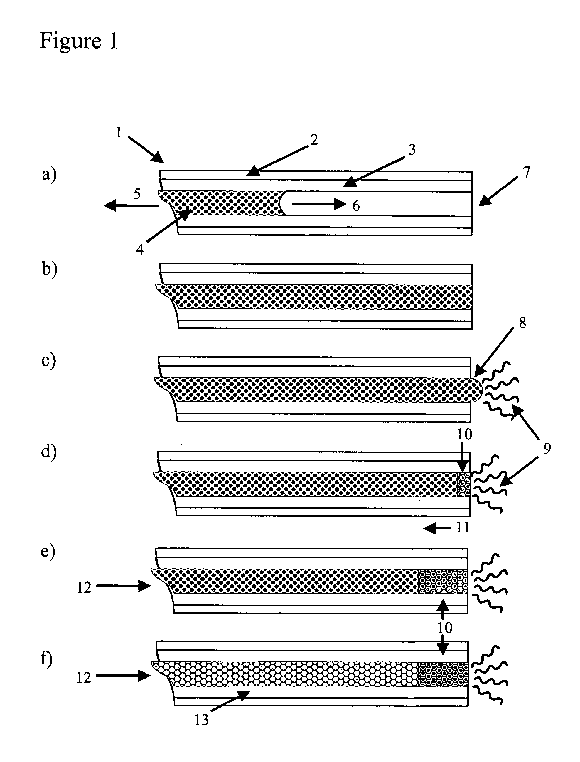
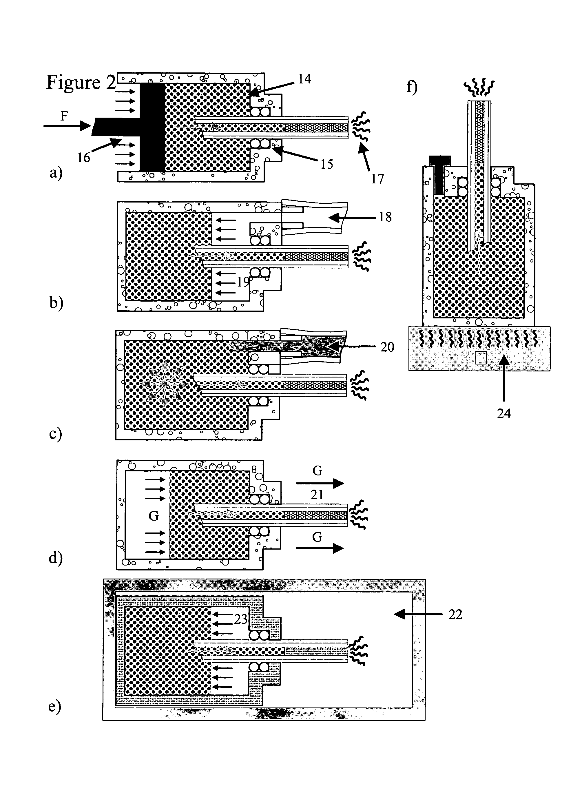
[0095] The present invention describes chromatographic devices employing a chromatographic column which, in one embodiment, is a photonic colloidal crystal which includes an assembly of colloidal microspheres formed into a column, and which, in a second embodiment is the inverted structure of the first embodiment, where solid microspheres making up the photonic colloidal crystal chromatographic column are replaced with spherical voids or void spaces embedded in a material of pre-selected index of refraction, in an elongate housing such as a capillary or as a free-standing column. Thus, the present invention provides two different types of photonic crystal columns, the first type of which is prepared using substantially monodisperse colloidal crystal particles assembled into a highly ordered array of particles within a housing such as a tube with the highly ordered array being a photonic crystal along the length of the crystal. The second type of photonic crystal column is produced b...


PUM

PropertyMeasurementUnit
Lengthaaaaaaaaaa
Diameteraaaaaaaaaa
Diameteraaaaaaaaaa

Abstract

The present invention provides a straightforward and robust synthetic process for producing a chromatographic column with eluent-sensitive light diffracting properties based on an inherent photonic band structure and a chromatographic device using the chromatographic column. The present invention provides chromatographic devices employing a chromatographic column which in one embodiment is a photonic colloidal crystal which includes an assembly of colloidal microspheres assembled into a highly ordered array within a housing such as a tube with the highly ordered array being a photonic crystal along the length of the crystal, and a second embodiment which is an inverse construct of the first embodiment, where solid microspheres making up the photonic colloidal crystal chromatographic column are replaced with spherical voids or void spaces subsequent to infiltration of a material of selected refractive index. The photonic band structures of the first type of column made with colloidal particles and the second type of column made by inverting the first type of column may include a photonic band gap, a fundamental stop-band, higher stop-bands, or combinations thereof.

Description

FIELD OF THE INVENTION [0001] The present invention is directed to a chromatographic apparatus which includes a photonic colloidal crystal column produced using an assembly of colloidal microspheres, or a photonic crystal column produced by inversion of the column made of colloidal particles in which solid microspheres are replaced with interconnected spherical voids embedded in a material of pre-selected index of refraction. The photonic crystal columns are formed in a capillary and may be used in that form in the capillaries or removed from the capillaries and used as a free-standing column. BACKGROUND OF THE INVENTION Photonic Crystals [0002] Photonic crystals interact strongly with electromagnetic radiation, when the periodicity of the photonic crystal corresponds to the scale of the wavelength of the electromagnetic radiation. The periodicity of the photonic crystal is achieved through a periodic modulation of the dielectric function. Due to the periodicity, photonic crystals ...

Claims


Application Information

Patent Timeline
IPC IPC(8): G02B6/00
CPCB01D15/22B01D15/3871G02B6/1225B82Y20/00G01N30/6082B01J20/282
Inventor KAMP, ULRICHKITAEV, VLADIMIRVON FREYMANN, GEORGOZIN, GEOFFREY ALANMABURY, SCOTT ANDREW
Owner THE GOVERNINIG COUNCIL OF THE UNIV OF TORANTO
Learn More