Terminal design with shock isolation assembly

a terminal design and shock isolation technology, applied in the field of portable electronic units, can solve the problems of increasing the weight of the unit by the same factor, affecting the stability of the unit, so as to prevent damage to electronic components, dampen an external mechanical shock, and dampen gradual effect of external mechanical shock

a terminal design and shock isolation technology, applied in the field of portable electronic units, can solve the problems of increasing the weight of the unit by the same factor, affecting the stability of the unit, so as to prevent damage to electronic components, dampen an external mechanical shock, and dampen gradual effect of external mechanical shock

US20050001037A1Active Publication Date: 2005-01-06SYMBOL TECH LLC

Image

  • Terminal design with shock isolation assembly
  • Terminal design with shock isolation assembly
  • Terminal design with shock isolation assembly

Examples


Embodiment Construction

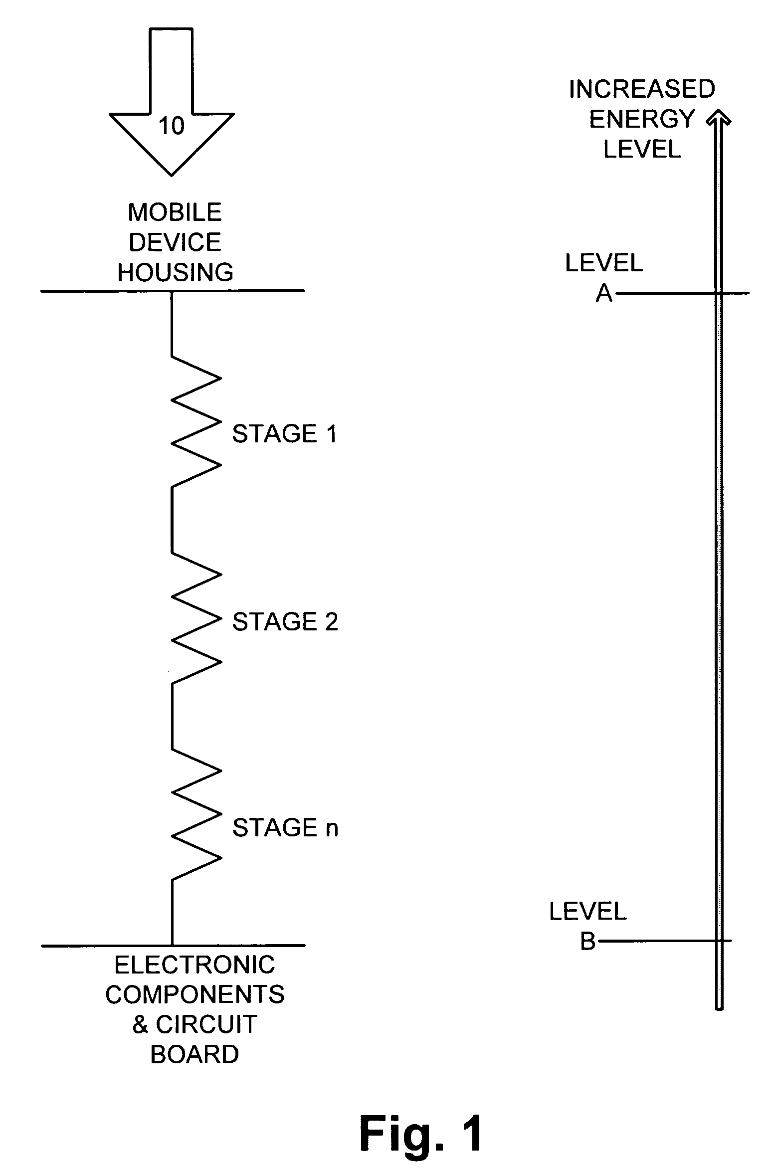
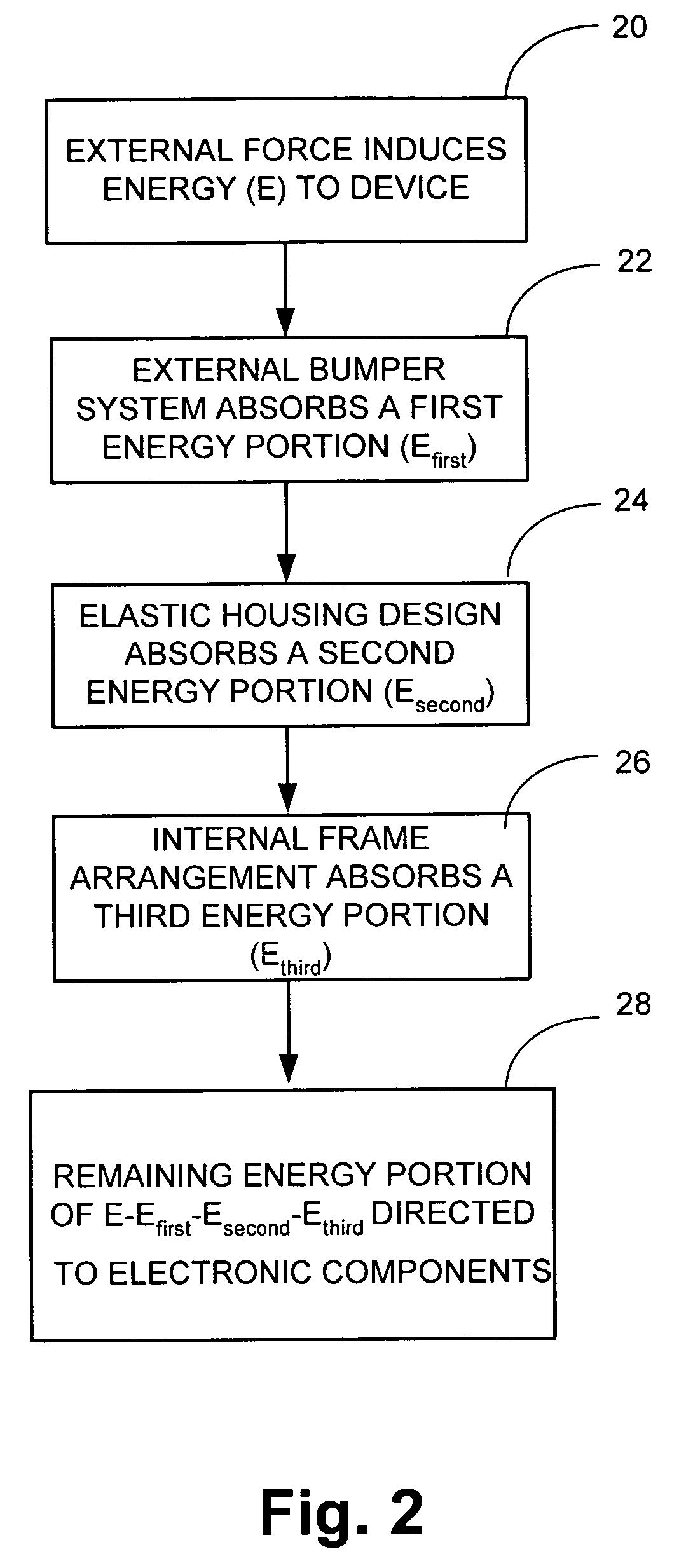
[0026] The various aspects of the present invention will now be described with reference to drawings. The invention provides for a system and methodology of isolating a portable electronic unit from external mechanical shocks and / or vibrations, so that the shock energy is significantly absorbed, and reduced to an acceptable safe limit by the time it reaches the electronic components.

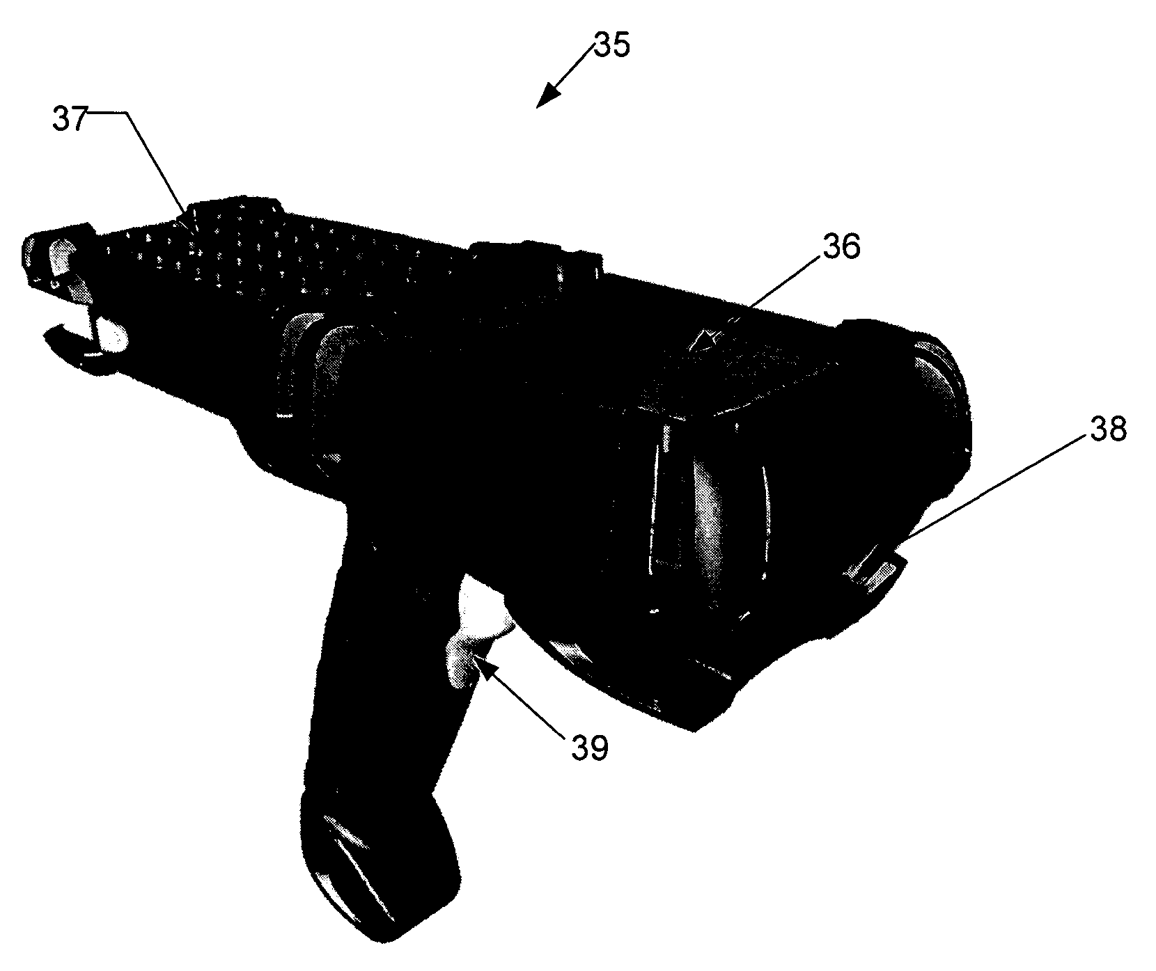
[0027] Referring initially to FIG. 1, an exemplary model that depicts one aspect of the subject invention is illustrated. A mobile unit is subjected to an external force as depicted by arrow 10. The mobile unit can be any hand held device with its internal electronic component, such as a circuit board with a Central Processing Unit (CPU) enclosed within a housing. The external force 10 can be induced via a mechanical shock, for example by dropping the unit on a hard surface.

[0028] Level A on the vertical energy axis depicts a level of energy created by external force 10 that can not be tolerated by the...


PUM


Abstract

Systems and methodologies are disclosed for isolating a portable hand held electronic unit from external mechanical shocks and / or vibrations by dampening them at several levels. The system can absorb an external mechanical shock at three different levels by employing an external bumper system, elastic housing design features, and an internal frame isolation. Moreover, such isolation assembly simplifies production of the portable electronic unit by enabling a “build to order process” according to a customer's specification.

Description

FIELD OF THE INVENTION [0001] The invention described below generally relates to systems and methods of shock isolation for a portable electronic unit, and in particular to an isolation assembly employing several stages of energy absorption for dampening an external mechanical shock. DESCRIPTION OF THE RELATED ART [0002] Typically there is a desire to increase the ruggedness for electronic units, while lowering associated assembly costs and improving overall function. In particular, many electronic units such as hand held mobile terminals, communication units, and the like are generally susceptible to damage during employment in harsh environments. Such units are generally assembled by enclosing internal electrical components, such as a central processing unit (CPU) board, display, keyboard, and internal wiring, within a housing made of plastic or another structural material. The enclosure normally serves as a protective measure and is typically formed in two parts having an upper h...

Claims


Application Information

Patent Timeline
06 Jan 2005
Publication
US20050001037A1
IPC
G06F1/16; G06K7/10; G06K9/22
CPC
G06F1/1626; G06K7/10881; G06F1/1684; G06F1/1656
Inventors
WULFF, THOMAS