Vehicle brake system for increasing friction coefficient

a technology of friction coefficient and brake system, which is applied in the direction of brake system, brake component arrangement, brake element arrangement, etc., can solve the problems of increasing the possibility of wheel slippage and other problems, and achieve the effect of reducing the friction coefficient of the road surface, increasing the friction coefficient, and lowering the electric resistance valu

Inactive Publication Date: 2005-01-06
ADVICS CO LTD
View PDF12 Cites 14 Cited by
  • Summary
  • Abstract
  • Description
  • Claims
  • Application Information

AI Technical Summary

Benefits of technology

[0013] When an outside temperature is within a preset temperature range including the water freezing point, it can be estimated that the road surface is in a near-frozen state, that is, the road is in a transitional state between water and ice (hereinafter, this state is referred to as a near-frozen state). In the near-frozen state, ice can be estimated as partially or completed melted, resulting in water present on the road surface. Accordingly, the friction coefficient of the road surface lowers due to the presence of water on the near-frozen road surface, and it can be assumed that operating the auxiliary braking mechanism will increase the friction coefficient.
[0014] When an electric resistance value on the traveled road surface is equal to or less than a preset resistance threshold value, it can be assumed that there is water present on the road surface which has lowered the electric resistance value. Accordingly, the friction coefficient lowers due to the presence of water on the traveled road surface, and it can be assumed that operating the auxiliary braking mechanism will increase the friction coefficient.
[0015] Furthermore, when a signal from a wiper switch is ON, that is, a wiper device is operating, the presence of water on the traveled road surface can be estimated. Accordingly, the friction coefficient lowers due to the presence of water on the traveled road surface, and it can be assumed that operating the auxiliary braking mechanism will increase the friction coefficient.

Problems solved by technology

However, if sand or the like is dispersed onto a dry road surface or road surface frozen at a very low temperature by the sand scattering device acting as an auxiliary braking mechanism, the friction coefficient (road surface μ) between the tire and road surface is lower than that before sand dispersal, and actually has the adverse effect of increasing the possibility of wheel slippage.

Method used


Image

  • Vehicle brake system for increasing friction coefficient
  • Vehicle brake system for increasing friction coefficient
  • Vehicle brake system for increasing friction coefficient

Examples


first embodiment

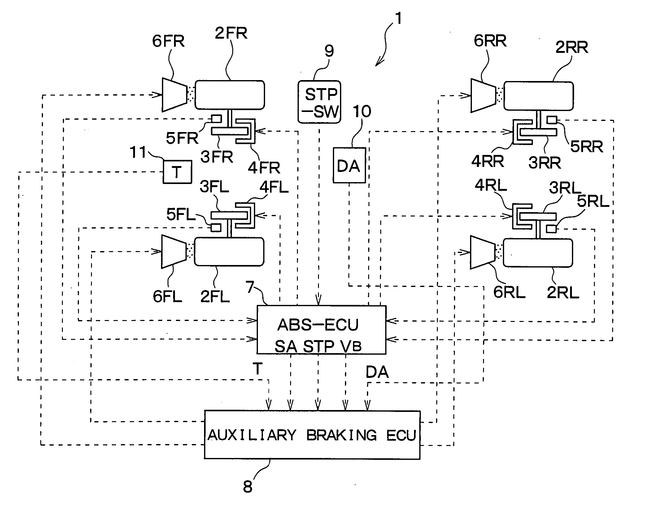
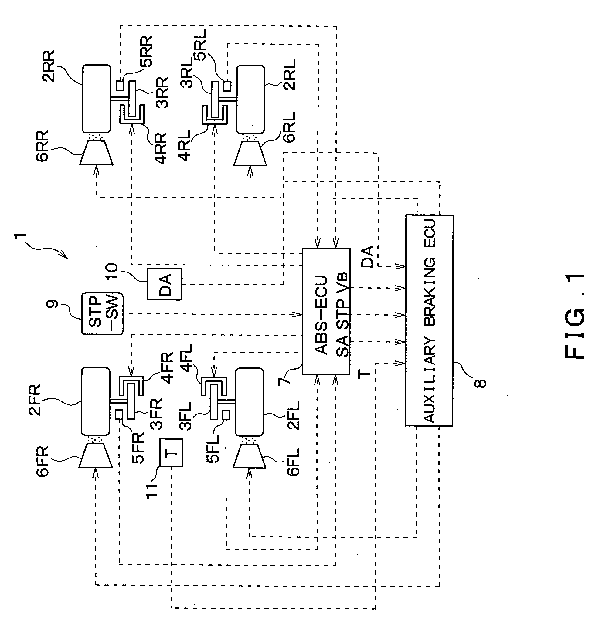
[0031]FIG. 1 is a schematic drawing showing an overall structure of a vehicle brake system according to a first embodiment of the present invention. The first embodiment is provided with an ABS control device (hereinafter referred to as ABS-ECU) 7 constructed from a microcomputer to operate an electromechanical brake device (hereinafter referred to as EMB) of each wheel. Note that a vehicle 1 is equipped with four wheels, each respectively provided with identical EMBs that are denoted as FR, FL, RR, and RL in FIG. 1. The front right wheel (FR) is described below, and descriptions of other wheels are omitted. In addition, a road surface friction coefficient that is the friction coefficient between a tire and road surface is hereinafter referred to as a road surface μ.

[0032] A disc rotor 3FR is mounted to a tire 2FR as a wheel, and integrally rotates with the tire 2FR. A caliper 4FR is provided such that the disc rotor 3FR is sandwiched therebetween. An electric motor (not shown) ser...

second embodiment

[0051] A second embodiment of the present will be described next. FIG. 3 is a schematic drawing showing an overall structure of a vehicle brake system according to the second embodiment of the present invention; FIG. 4 is a drawing of the vehicle 1 according to the second embodiment viewed from the front; and FIG. 5 is a flowchart showing processing of a program that executes an auxiliary brake control in the second embodiment. It should be noted that structures and processing similar to the above first embodiment are identically numbered and descriptions thereof are omitted.

[0052] The vehicle brake system according to the second embodiment differs from the first embodiment in that an electric resistance measuring unit 12 is provided in place of the acceleration sensor 10 and the outside temperature sensor 11.

[0053] The electric resistance measuring unit 12, as shown in FIG. 4, is provided on an under surface of the vehicle 1 between front right and left wheels 2FR, 2FL, and a det...

third embodiment

[0058] A third embodiment of the present invention will be described next. FIG. 6 is a schematic drawing showing an overall structure of a vehicle brake system according to the third embodiment of the present invention, and FIG. 7 is a flowchart showing processing of a program that executes an auxiliary brake control in the third embodiment. It should be noted that structures and processing similar to the above first and second embodiments are identically numbered and descriptions thereof are omitted.

[0059] The vehicle brake system according to the third embodiment differs from the first embodiment in that a wiper switch (wiper SW) 13 is provided in place of the acceleration sensor 10 and the outside temperature sensor 11. When a wiper device to wipe water droplets from a front windshield is automatically or manually turned ON to operate, the wiper SW 13 supplies a wiper operation signal WP to the auxiliary brake ECU 8 in response to the ON state. That is, it can be estimated from ...


PUM


Abstract

An auxiliary braking mechanism is operated to increase a braking effect, only after it is determined whether adding the auxiliary braking mechanism during vehicle braking by a main braking mechanism will increase the braking effect. In the case where a main braking force is generated on a tire by pressing of friction material in a caliper on a disc rotor, and an approximate speed from an acceleration sensor is smaller than a predetermined value, while an outside temperature from an outside temperature sensor is within a predetermined temperature range including the freezing point, an auxiliary brake ECU estimates that water or a mixture of water and ice are present on a frozen road surface, determines that a road surface μ can be increased through operation of the auxiliary braking mechanism, and scatters sand on the road surface using a particle scattering device. Thus, it is possible to prevent lowering of the road surface μ by scattering sand on the completely frozen road surface.

Description

CROSS REFERENCE TO RELATED APPLICATION [0001] This application is based upon and claims the benefit of Japanese Patent Applications No. 2003-173829 filed on Jun. 18, 2003 and No. 2004-94921 filed on Mar. 29, 2004, the content of which are incorporated herein by reference. FIELD OF THE INVENTION [0002] The present invention relates to a vehicle brake system that increases a friction coefficient between a wheel and road surface by combining use of a main braking mechanism that is a normal brake device, such as a hydraulic brake device, electromechanical brake device, or regenerative brake device, with an auxiliary braking mechanism other than the main braking mechanism. BACKGROUND OF THE INVENTION [0003] A sand scattering device in a vehicle, such as disclosed in Published Unexamined Utility Model Application No. 54-172439, drops sand on a road surface along a tire through operation of a switch in order to increase the friction coefficient between the tire and road surface. [0004] How...

Claims


Application Information

Patent Timeline
Patent Type & Authority Applications(United States)
IPC IPC(8): B60B39/04B60T1/14
CPCB60T1/14B60B39/04
Inventor WATANABE, TAKASHIMASAKI, SHOICHISAKAI, MORIHARU
Owner ADVICS CO LTD
Why Eureka
Try Eureka