Cathode-ray tube

a cathode-ray tube and tube body technology, applied in the field of cathode-ray tubes, can solve the problems of varying electron emission regions, affecting the display quality, and affecting the display quality, and achieve the effect of high display quality

Inactive Publication Date: 2005-01-06
KK TOSHIBA
View PDF3 Cites 2 Cited by
  • Summary
  • Abstract
  • Description
  • Claims
  • Application Information

AI Technical Summary

Benefits of technology

[0018] The present invention has been made in consideration of the above-described problems, and its object is to provide a cathode-ray tube with high display quality.

Problems solved by technology

Thus, an electron emission region for emitting electrons is not formed on the cathode K. On the other hand, as shown in FIG. 9B, the application of the drive voltage causes imbalance between the permeating electric field and the cathode potential.
However, the electron gun assembly, which controls the electron beam amount by the above scheme, has two potential problems, as described below.
The first problem is due to the fact that the electron emission region varies depending on the magnitude of the drive voltage.
Hence, if the drive voltage is low, that is, if the electron beam amount (cathode current amount) is small, the beam spot size decreases, and such a problem as the occurrence of moiré arises.
When the electron beam amount (cathode current amount) is large, the beam spot size increases, and such a problem as degradation in resolution arises.
The second problem is due to the fact that a current emitted from the cathode has a density distribution, as shown in FIG. 11, since the intensity of the permeating electric field becomes maximum at the center of the cathode.
In the case where the area of the electron emission region is large, the current density at an end part of the electron emission region (i.e. at a location away from the center of the cathode) is low, and a sufficient amount of electrons cannot be produced.
However, since the cathode-ray tube is generally used at high frequencies, the applicable drive voltage is limited.
The first problem is the occurrence of moiré at a time of low current and the degradation in resolution at a time of high current time, since the beam spot size varies depending on the magnitude of drive voltage.
The second problem is that since the electric field intensity at the end part of the electron emission region, which greatly affects the cathode current amount, is small, the cathode is not efficiently used and the cathode current amount cannot be increased.
However, this holds true only when the cathode current is small (at a time of low current).
The reason is that in actual cases, if the current has a certain value or more, a repulsion effect due to space charge becomes unignorable.
In particular, at a time of high luminance (high current), this effect becomes more conspicuous and the object point size cannot sufficiently be improved.
This results in a considerable degradation in electron beam size at a time of high current.
In this case, however, there arises an adverse effect due to a spherical aberration of the main lens section.
In consideration of the space charge repulsion effect occurring between the main lens section and the phosphor screen and at the region of the cross-over, the above-described electron gun assembly can hardly improve the resolution at the time of high luminance display.
Rather, in some cases, the resolution may deteriorate.

Method used


Image

  • Cathode-ray tube
  • Cathode-ray tube
  • Cathode-ray tube

Examples


Embodiment Construction

[0039] A cathode-ray tube according to an embodiment of the present invention will now be described with reference to the accompanying drawings.

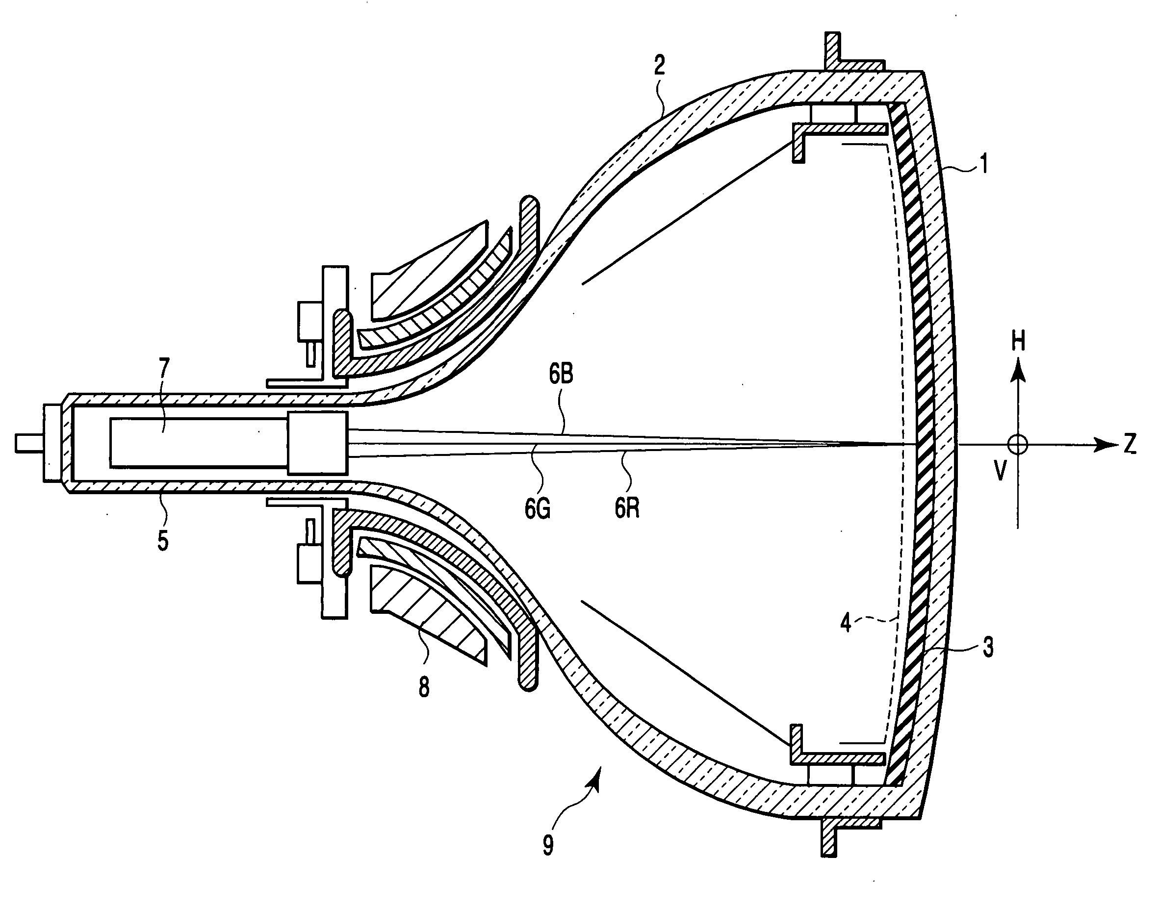
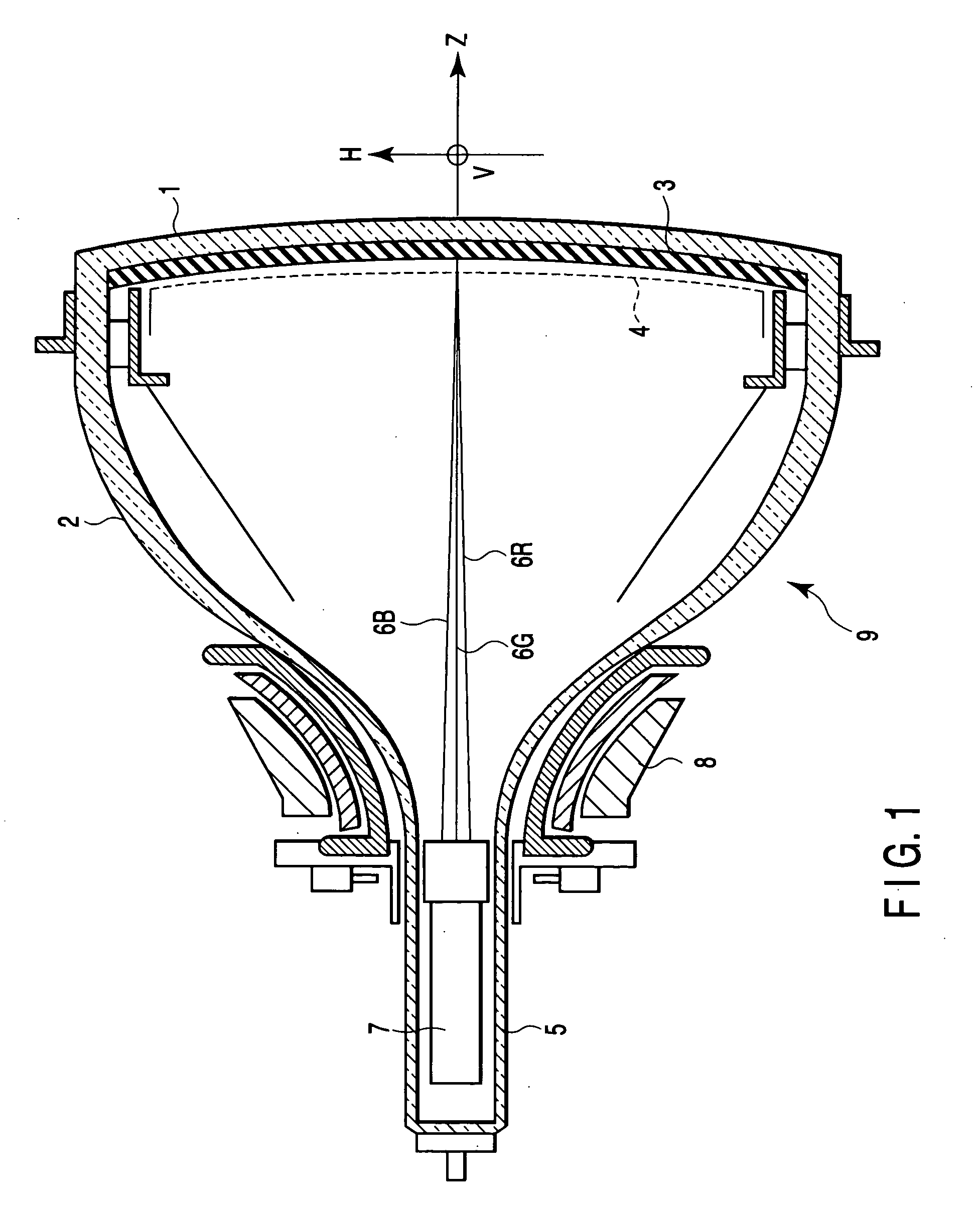
[0040] As is shown in FIG. 1, a cathode-ray tube apparatus, that is, a self-convergence type in-line color cathode-ray tube apparatus, has a vacuum envelope 9. The vacuum envelope 9 includes a panel 1 and a funnel 2 integrally coupled to the panel 1. A phosphor screen 3 is disposed on an inside surface of the panel 1. The phosphor screen 3 has three-color striped or dot-shaped phosphor layers, which emit blue, green and red light. A shadow mask 4 is disposed to face the phosphor screen 3. The shadow mask 4 has many apertures in its inside part.

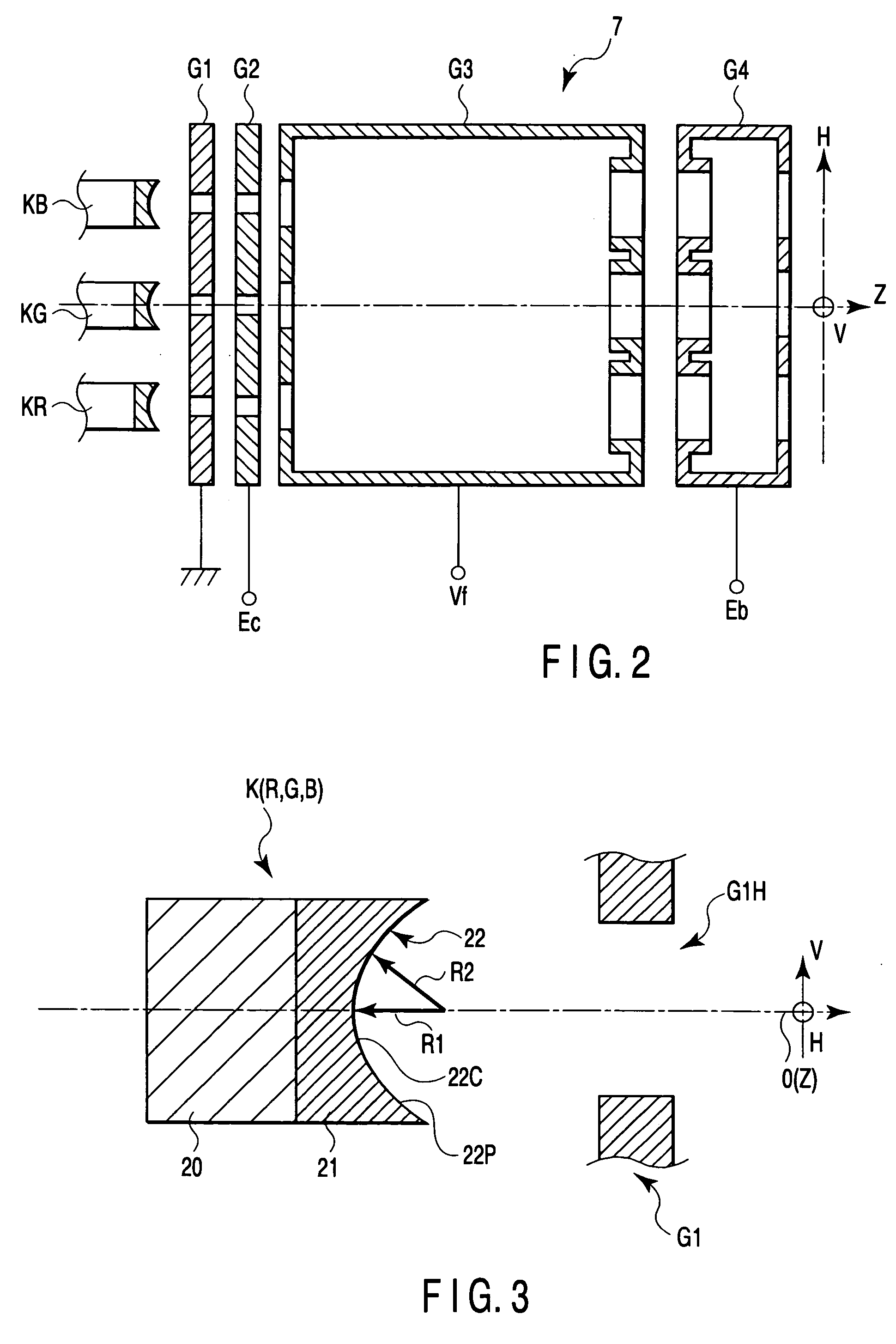
[0041] An in-line electron gun assembly 7 is disposed within a cylindrical neck 5, which corresponds to a small-diameter portion of the funnel 2. The electron gun assembly 7 emits three in-line electron beams 6B, 6G and 6R (i.e. a center beam 6G and side beams 6B and 6R) which are arranged in line an...


PUM


Abstract

An electron beam generating section of an electron gun assembly includes at least a cathode that emits an electron beam, and a control electrode that is disposed on a phosphor screen side of the cathode. The cathode has a cathode face that is opposed to the control electrode, the cathode face having a concave shape with a recessed central portion. The electron beam that is emitted from the cathode face forms a cross-over with a tube axis. A cross-over point of an electron beam, which is emitted from the central portion of the cathode face, differs from a cross-over point of an electron beam, which is emitted from an off-axis portion of the cathode face.

Description

CROSS-REFERENCE TO RELATED APPLICATIONS [0001] This application is based upon and claims the benefit of priority from prior Japanese Patent Application No. 2003-172369, filed Jun. 17, 2003, the entire contents of which are incorporated herein by reference. BACKGROUND OF THE INVENTION [0002] 1. Field of the Invention [0003] The present invention relates generally to a cathode-ray tube with an electron gun assembly that emits at least one electron beam, and more particularly to a cathode-ray tube capable of enhancing focus characteristics of an electron beam and drive characteristics, thereby realizing high luminance and high resolution over the entirety of a screen. [0004] 2. Description of the Related Art [0005] As is shown in FIG. 8, an in-line electron gun assembly, which is applied to a prior-art color cathode-ray tube, comprises cathodes K having electron emission materials on their faces opposed to a first grid G1; the first grid G1; a second grid G2; a third grid G3; and a fou...

Claims


Application Information

Patent Timeline
Patent Type & Authority Applications(United States)
IPC IPC(8): H01J29/04H01J3/02H01J23/08H01J29/48
CPCH01J3/027H01J29/488H01J3/029
Inventor ONO, OSAMU
Owner KK TOSHIBA
Why Eureka
Try Eureka