Electronic still camera and system and program for same

a technology of electronic still camera and camera, which is applied in the field of electronic still camera and electronic still cameral system, can solve the problems of limited storage continuous frame count, user inability to fully take advantage of the features of storage medium, and the possibility of increasing the storage continuous frame coun

Inactive Publication Date: 2005-01-06
NIKON CORP
View PDF12 Cites 35 Cited by
  • Summary
  • Abstract
  • Description
  • Claims
  • Application Information

AI Technical Summary

Benefits of technology

[0012] In view of solving the foregoing problems of the above-mentioned prior art technique, an object of the present invention is to provide an electronic still camera that allows the user to accurately know, before shooting, a storable continuous frame count of an electronic still camera and a continuous shooting rate of frames of when an actual continuous frame count exceeds the storable continuous frame count.

Problems solved by technology

When a storage medium whose storing rate is lower than the internal processing rate of the electronic still camera, the storable continuous frame count is limited by the storing rate of the storage medium.
If such a storage medium is used with an electronic camera, it is not possible to increase the storable continuous frame count because of the lower storing rate of the camera.
As a result, the user cannot fully take advantage of the features of the storage medium, and on that point conventional cameras have to be modified.
However, in this case, the user cannot know of how many continuous frames are stored; therefore, the storage medium cannot meet the users' needs sufficiently.
Besides, the user may not obtain desired images if he or she uses a storage medium with a lower storing rate because the user cannot know the continuous shooting rate of frames of when an actual continuous frame count exceeds the storable continuous frame count.
Furthermore, according to the technique disclosed in the above-mentioned Publication No. 2001-169227, the user cannot obtain accurate information on residual storage time and so forth at initial shooting or setting changes of the electronic still camera because the information is obtained according to the storing rate at which previous moving images were shot.
Moreover, it cannot solve the problems unique to the electronic still camera such as a decrease of the continuous shooting rate of frames of when an actual continuous frame count exceeds the storable continuous frame count.

Method used


Image

  • Electronic still camera and system and program for same
  • Electronic still camera and system and program for same
  • Electronic still camera and system and program for same

Examples


first embodiment

[0051] (Structure of First Embodiment)

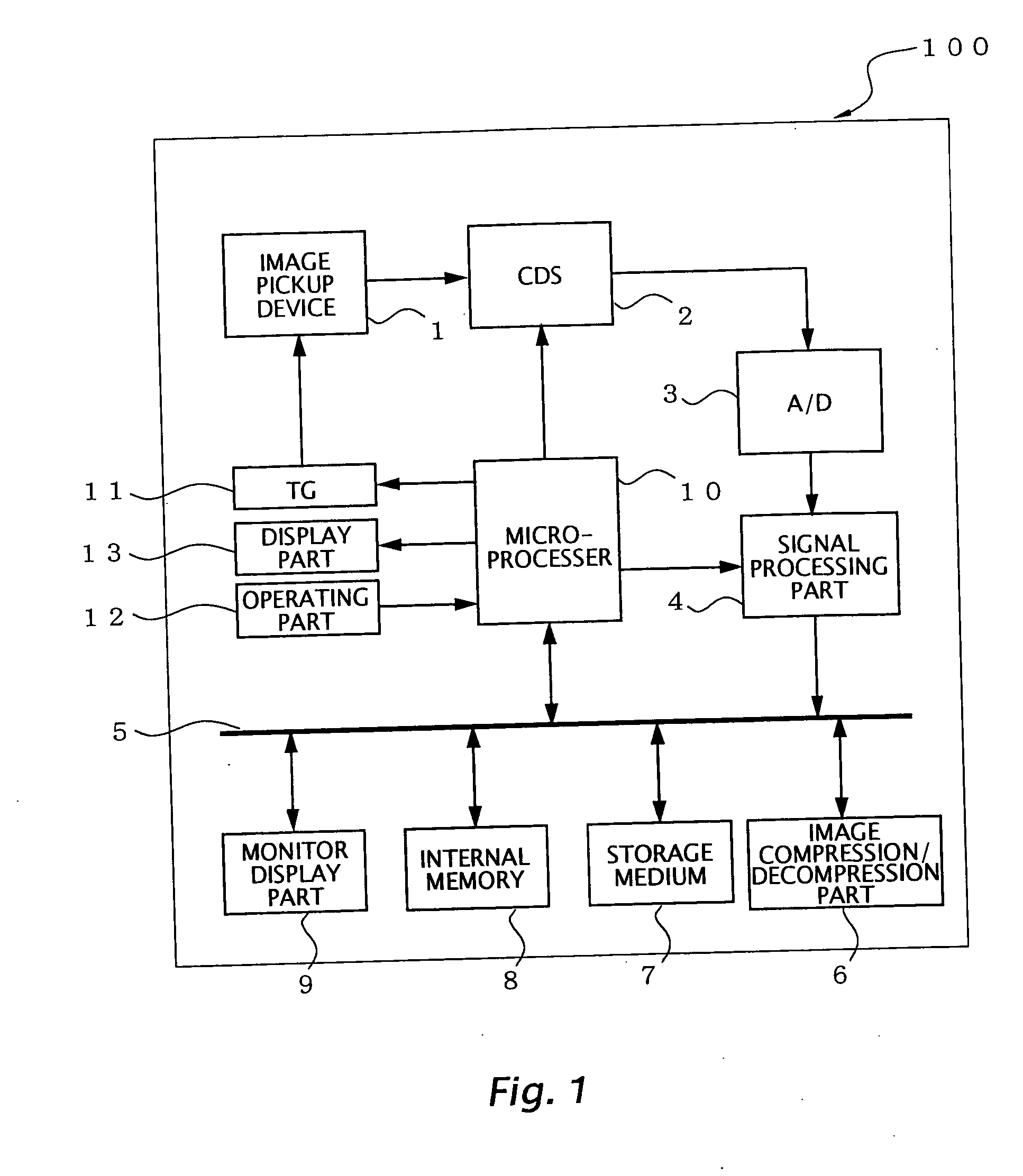
[0052]FIG. 1 is a schematic diagram showing a structure of an electronic still camera 100 according to a first embodiment of the present invention. An image pickup device 1 is disposed on an image space of a shooting lens (not shown). Light receiving elements are two-dimensionally arranged on a light receiving plane of the image pickup device 1. An object image is projected on the light receiving plane of the image pickup device 1 and photoelectrically converted by the light receiving elements of the image pickup device 1, thereby generating image signals that compose image data.

[0053] An output of the image pickup device 1 is connected to a signal processing part 4 through a CDS circuit 2 and an A / D converting circuit 3. The signal processing part 4 performs an interpolation processing and so forth on image data. An output signal of the signal processing part 4 is connected to a bus 5.

[0054] An image compression / decompression part 6, a storag...

second embodiment

[0086] (Second Embodiment)

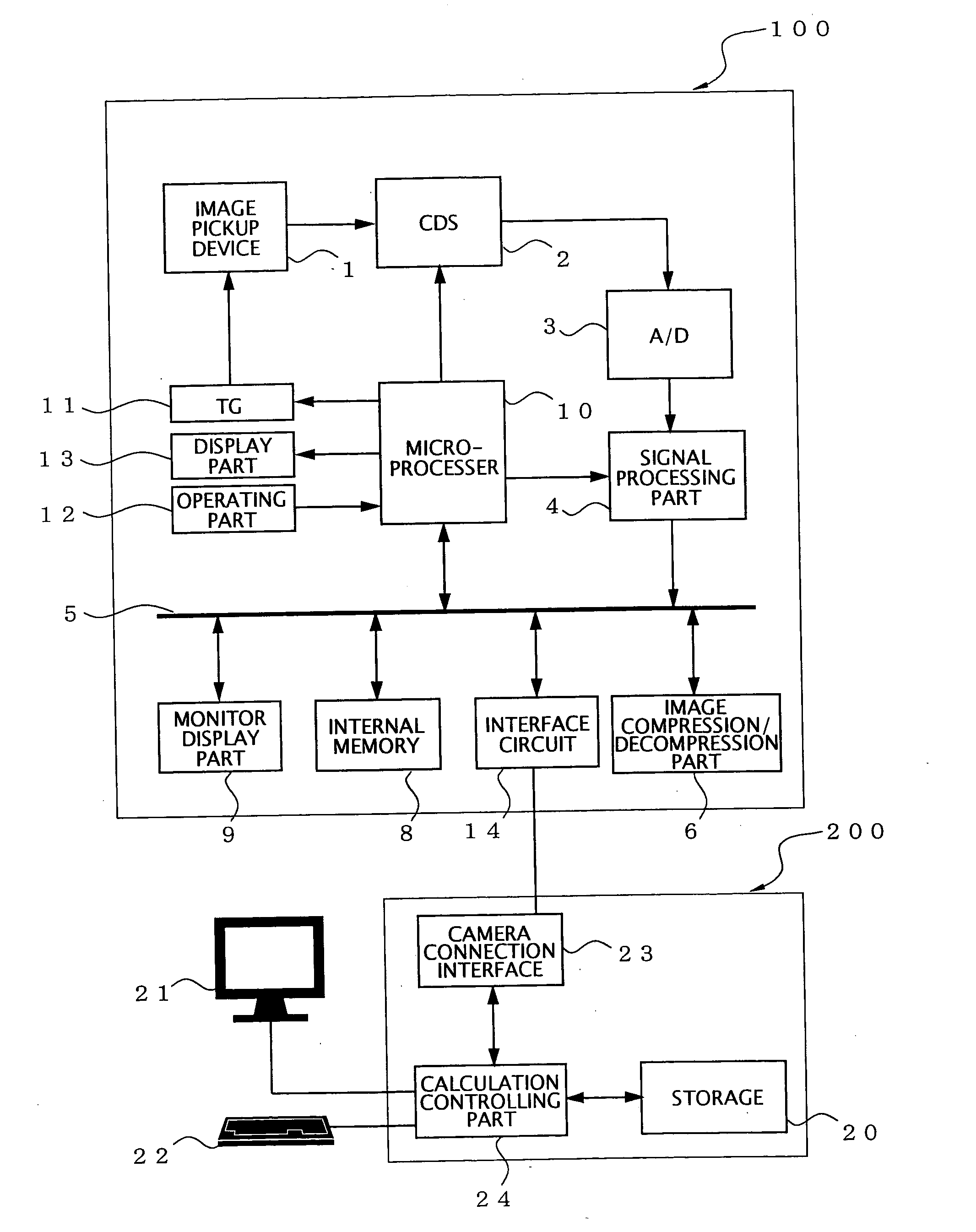
[0087]FIG. 3 is a schematic diagram showing a structure of an electronic still camera system according to a second embodiment of the present invention. For simplicity, the same parts herein as those in the first embodiment will be denoted by similar reference numerals and their description will be omitted.

[0088] In the electronic still camera system according to the second embodiment, an electronic still camera 100 is connected with an outboard storage 200 to store image data therein. The outboard storage 200 according to the second embodiment has a storage 20 that stores image data, a display part 21 such as a monitor, an input part 22, a camera connection interface 23, and a calculation controlling part 24 that controls each part of the outboard storage 200. The outboard storage 200 may be for example a storage that is directly connectable to the electronic still camera 100, a stand-alone type personal computer, or a network computer composed of a server...


PUM


Abstract

The electronic still camera includes an internal memory, a calculating part, a storage medium, and a display part. With a storing rate of the storage medium equal to or higher than an internal processing rate of the camera, the calculating part calculates a storable continuous frame count according to a residual storage capacity and an image data amount of the storage medium. With the storing rate lower than the internal processing rate, it calculates the same according to a storage capacity of the internal memory, the image data amount, a continuous shooting rate of frames, the internal processing rate, and the storing rate, and calculates the continuous shooting rate of frames of when an actual continuous frame count exceeds the storable continuous frame count according to the storing rate and image data amount. The display part displays the storable continuous frame count and continuous shooting rate of frames.

Description

CROSS REFERENCE TO RELATED APPLICATION [0001] This application is based upon and claims the benefit of priority from Japanese Patent Application No. 2003-189577, filed on Jul. 1, 2003, the entire contents of which are incorporated herein by reference. BACKGROUND OF THE INVENTION [0002] 1. Field of the Invention [0003] The present invention relates to an electronic still camera and an electronic still cameral system, in particular, to ones that provide, in accordance with a storing rate of a storage medium, a storable continuous frame count and a continuous shooting rate of frames at a time when an actual continuous frame count exceeds the storable continuous frame count. [0004] 2. Description of the Related Art [0005] At continuous shooting by use of a conventional electronic still camera, image data of a shot object is temporarily stored in an internal memory and then is stored in a storage medium that is composed of semiconductor memories such as a compact flash memory, to finish ...

Claims


Application Information

Patent Timeline
Patent Type & Authority Applications(United States)
IPC IPC(8): H04N5/225H04N5/77H04N5/907H04N5/91H04N9/804H04N101/00
CPCH04N5/77H04N9/8047H04N5/907H04N5/772
Inventor SUZUKI, MASAHIRO
Owner NIKON CORP
Why Eureka
Try Eureka