Time-of-day apparatus receiving standard time code broadcast

a time-of-day apparatus and broadcast technology, applied in the field of time-of-day apparatus for receiving a standard time-of-day broadcast, can solve the problems of significant error in the display time-of-day, and deterioration in the receiving condition of the radio-wave clock

Inactive Publication Date: 2005-01-06
LAPIS SEMICON CO LTD
View PDF9 Cites 10 Cited by
  • Summary
  • Abstract
  • Description
  • Claims
  • Application Information

AI Technical Summary

Problems solved by technology

For example, if the radio-wave clock is placed in a house with steel-reinforced concrete walls or on a basement floor of a building, the receiving condition would significantly be deteriorated because of the attenuation of the arriving wave.
Also, if there exist a number of sources of radio wave noises around the radio-wave clock, the receiving condition of the radio-wave clock would be deteriorated by the influence of such noises.
When the reception fail state continues for a long time, however, there is a possibility of causing an error in the display time-of-day depending on the accuracy of a crystal oscillator used for a quartz oscillating circuit included in the radio-wave clock.
Accordingly, in order to decrease the error of the display time-of-day, it is necessary to use a crystal oscillator of high accuracy and naturally this increases the manufacturing cost disadvantageously.
Accordingly, when the time intervals of the intermittent operation are expanded, the power consumption can be saved, but when the receiving condition is deteriorated, the reception fail state continues for a long time and an error in the displayed time-of-day is easy to happen.
While, when the time intervals are shortened, an error in the display time-of-day can be decreased even in the case where the receiving condition is deteriorated, but the power consumption is increased disadvantageously.

Method used


Image

  • Time-of-day apparatus receiving standard time code broadcast
  • Time-of-day apparatus receiving standard time code broadcast
  • Time-of-day apparatus receiving standard time code broadcast

Examples


first embodiment

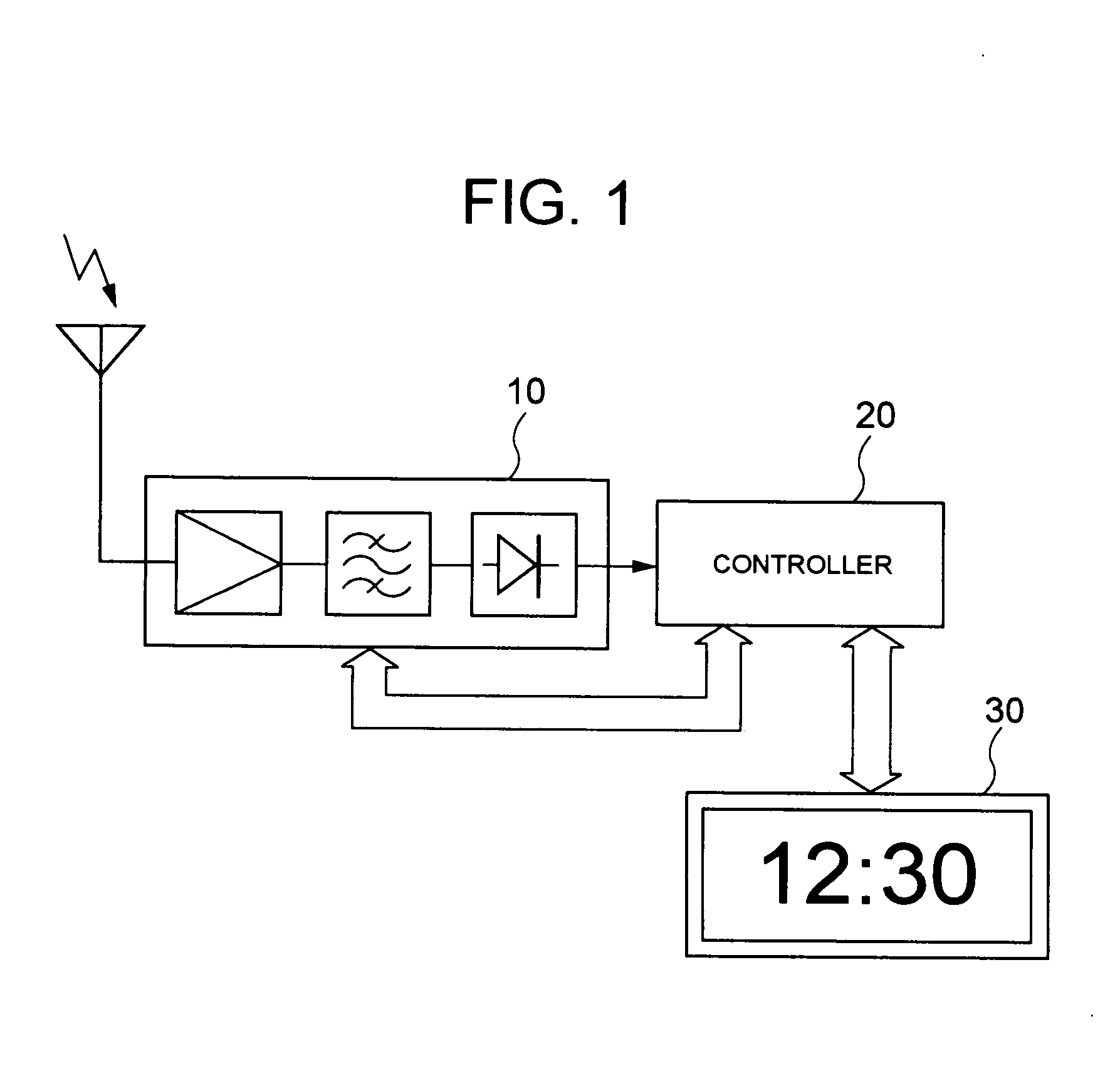
the standard broadcast receiving time-of-day apparatus according to the invention will be described based on the block diagram of FIG. 1.

As shown in FIG. 1, the system according to this embodiment chiefly comprises a radio receiver unit 10, a controller 20, and a clock unit 30.

The radio receiver unit 10 is mainly formed by the circuits including a receiving antenna, a high frequency amplifier, a band-pass filter, and a detector, and it plays a role of receiving, detecting, and demodulating the standard broadcast. Although it is not shown in FIG. 1, it is needless to say that the radio receiver unit 10 includes various auxiliary circuits including an AGC circuit and an AFC circuit which are naturally to be equipped in a general low frequency receiver.

The controller 20 is constituted mainly of a microcomputer, memories such as ROM and RAM, and various circuits of the peripheral units (none of which are illustrated). In the memories, a main program and various kinds of subprograms...

fourth embodiment

the standard broadcast receiving time-of-day apparatus according to the invention will be described.

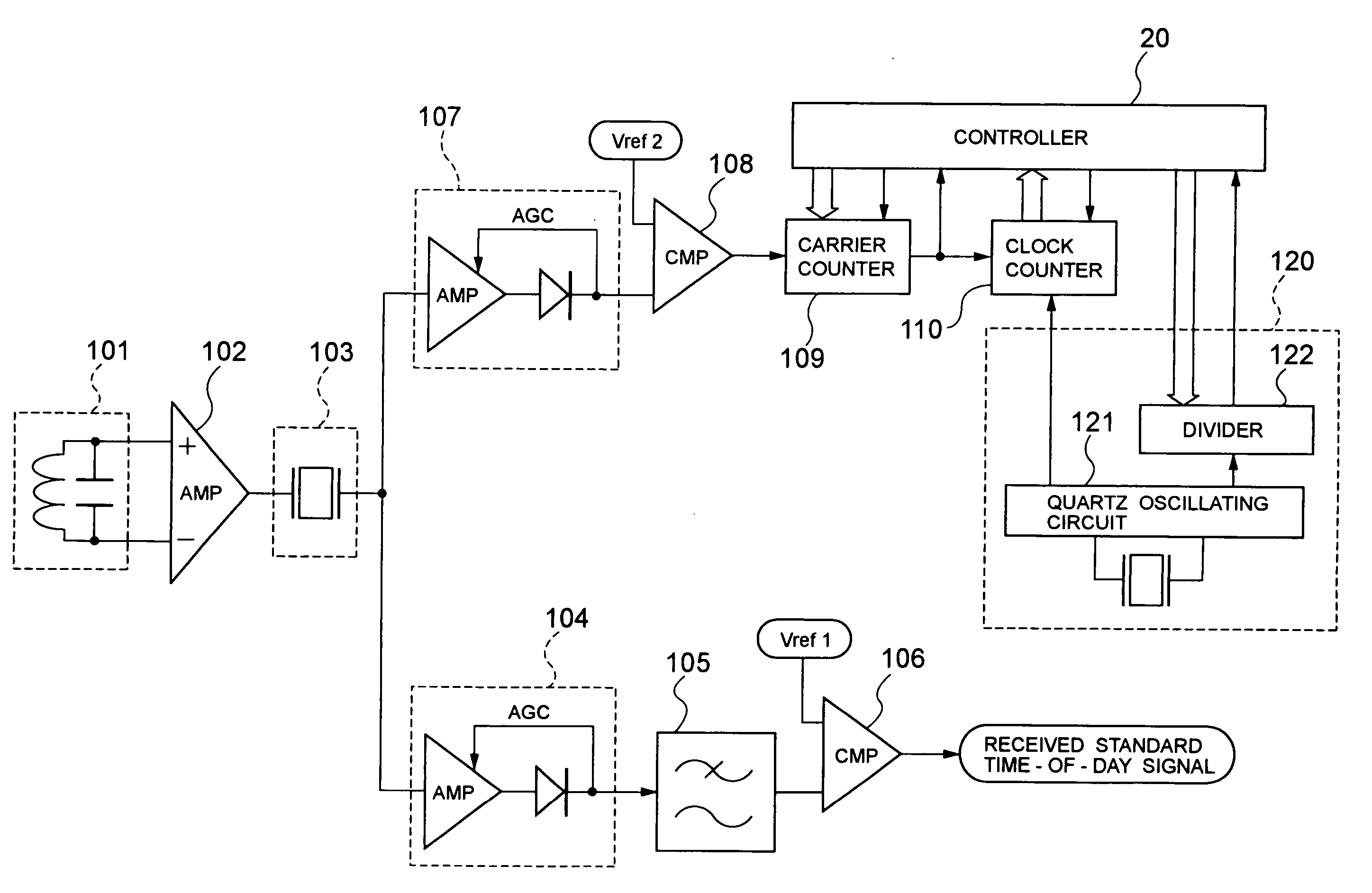
The structure of the system in the embodiment is shown in the block diagram of FIG. 5. The block diagram is to show only the portions concerned with the embodiment of the invention, and the description of the portions not directly concerned with the embodiment of the invention, for example, the description of the display of the time and its driving circuit, is omitted.

The structure of the embodiment will be described with reference to FIG. 5.

An antenna 101 in FIG. 5 is a low frequency receiving antenna such as a loop antenna and a ferrite antenna. The standard broadcast of low frequency transmitted from the standard broadcast station is modulated by the antenna 101 and received by the system as a feeble signal.

The high frequency amplifier 102 is a high frequency amplifier for amplifying a feeble received signal from the antenna 101 to a predetermined level, and the signal ampli...

sixth embodiment

the standard broadcast receiving time-of-day apparatus according to the invention will be described.

The structure of the system according to the embodiment is shown in the block diagram of FIG. 7. This block diagram is to show only the portions concerned with the embodiment of the invention, but the description of the portions not directly concerned with the embodiment of the invention, for example, the description of the time-of-day display and the driving circuit is omitted.

The structure of the embodiment will be described with reference to FIG. 7. This embodiment is based on the fifth embodiment, and to calibrate the internal clock frequency by using the carrier frequency of the standard broadcast as a reference clock of the PLL circuit. Therefore, only the portions added to the structure of the fifth embodiment are described hereafter.

In FIG. 7, a connection switch 310 is a signal switching circuit by using an analog signal switching element such as analog switch and a merc...


PUM


Abstract

A standard broadcast receiving time-of-day apparatus capable of using a crystal oscillator of low accuracy and saving the power consumption. This includes a receiver for receiving the standard broadcast, a time unit using a quartz oscillating circuit, and a time controller for calibrating an internal time-of-day signal which the time unit counts by using the standard time-of-day signal superimposed on the standard broadcast, and the time controller requires and stores a deviation between the internal time-of-day signal and the standard time-of-day signal and calibrates the internal time-of-day signal by using the stored deviation when failing to receive the standard broadcast. A clock pulse extracted from the carrier wave of the standard broadcast may be counted for a predetermined period and the frequency deviation of an internal clock may be calibrated by checking the count number of the internal clock counted for the above period. Or, the internal clock may be calibrated by using the carrier wave of the standard broadcast as a reference clock of the PLL circuit.

Description

BACKGROUND OF THE INVENTION 1. Field of the Invention The present invention relates to a time-of-day apparatus for receiving a standard time code broadcast and performing time-of-day calibration. 2. Description of the Related Art Japan Standard Time is consistently transmitted by means of LF (low frequency) broadcasts from two stations in Japan which are directly managed by the independent corporation, Communications Research Laboratory. Hereafter, the LF broadcast for transmitting the Japan Standard Time described above is referred to as “Standard Broadcast.” Currently, there are two standard broadcasts respectively of carrier frequencies 40 kHz and 60 kHz, and these LF waves of the different carrier frequencies are transmitted respectively from the above stations. The carrier wave of the standard broadcast is subjected to the pulse amplitude modulation, according to the time-of-day data pulse string of the Japan Standard Time converted into the digital signal of a predetermin...

Claims


Application Information

Patent Timeline
Patent Type & Authority Applications(United States)
IPC IPC(8): G04G3/02G04G5/00G04R20/08G04R40/04G04R60/14H04N7/00
CPCG04G3/02G04R20/08G04R40/06G04G5/002
Inventor KONDO, TAKAYUKI
Owner LAPIS SEMICON CO LTD
Why Eureka
Try Eureka