

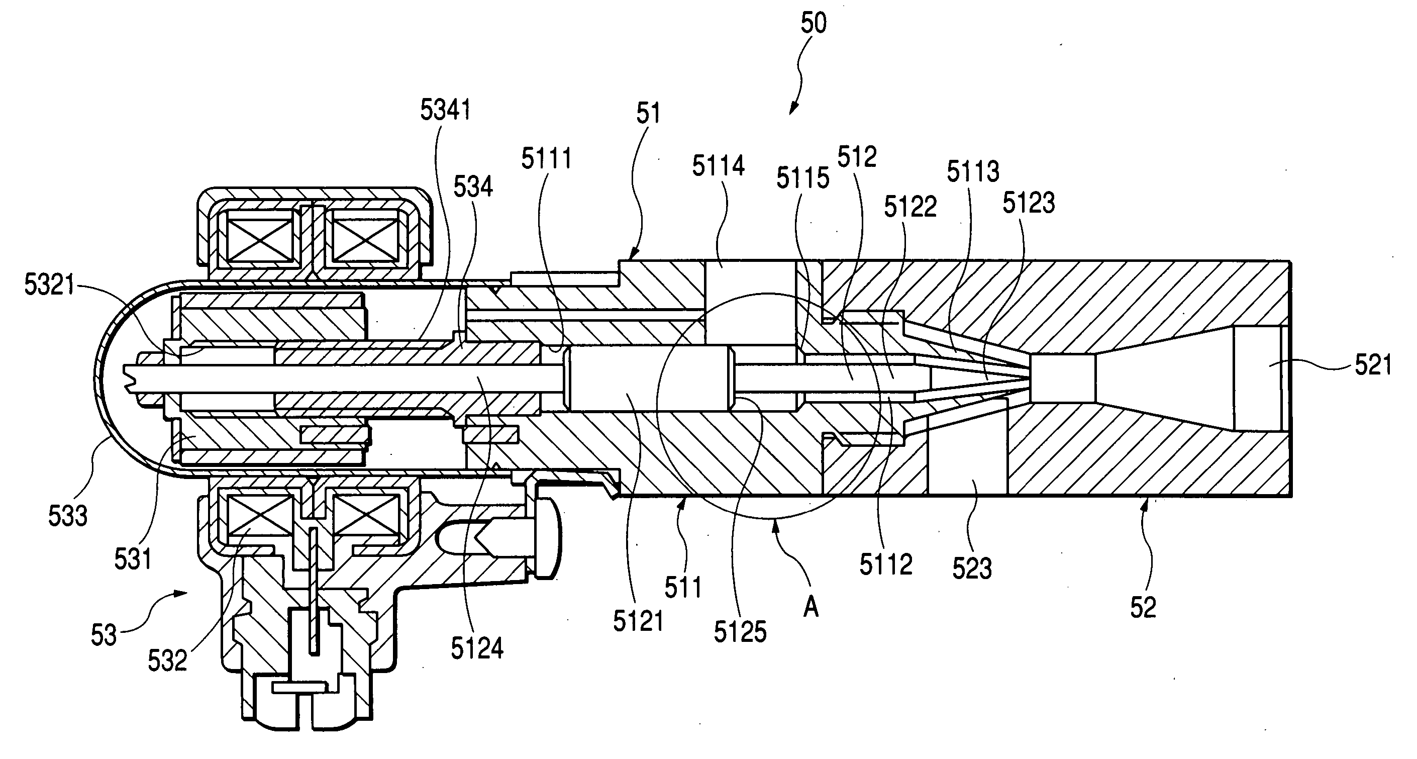
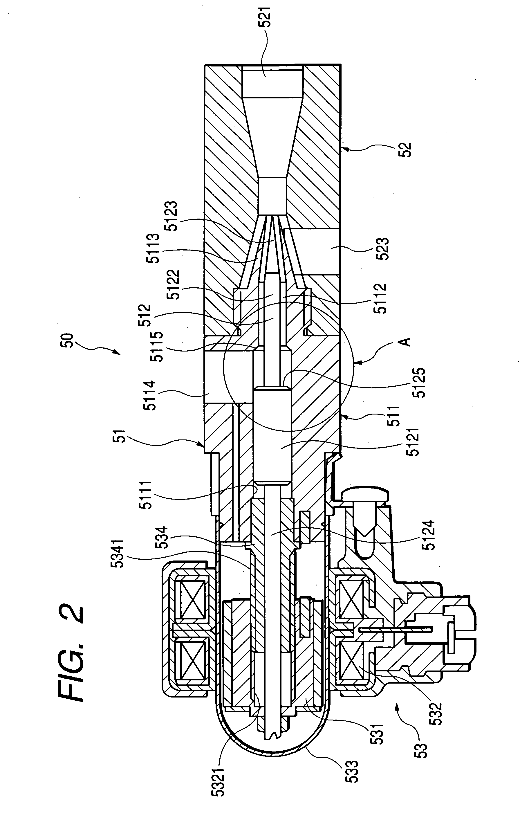
Structure of ejector pump
a technology of ejector pump and structure, which is applied in the direction of electrochemical generators, machines/engines, mechanical apparatuses, etc., can solve the problems of inability to circulate off-gas, inability to operate fuel cells, and inability to achieve the effect of increasing the dynamic energy of the main fluid
- Summary
- Abstract
- Description
- Claims
- Application Information
AI Technical Summary
Benefits of technology
Problems solved by technology
Method used
Image

Examples
Embodiment Construction
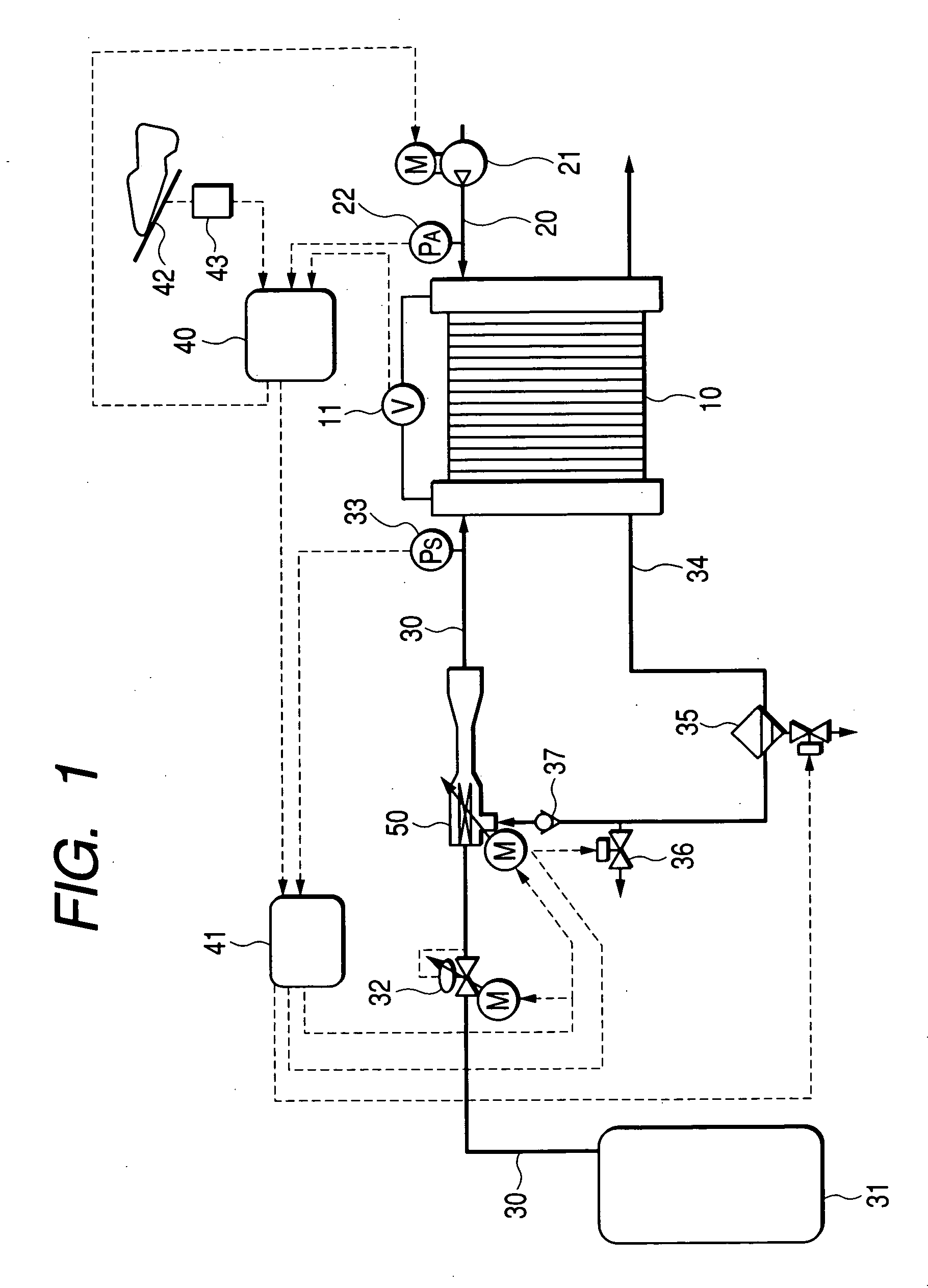
[0031] Referring to the drawings, wherein like reference numbers refer to like parts in several views, particularly to FIG. 1, there is shown a fuel cell system according to the first embodiment of the invention. The fuel cell system is illustrated, as an example, as being used as a power source to propel an electric vehicle (i.e., a fuel cell-powered vehicle).
[0032] The fuel cell system consists essentially of a fuel cell stack 10, an air supply device 21, a fuel supply device 31, an ejector pump 50, and controllers 40 and 41.
[0033] The fuel cell stack 10, as is well known in the art, works to convert energy produced by electrochemical reaction of oxygen and hydrogen (i.e., fuel) into electric power. The fuel cell stack 10 is made up of a plurality of solid polyelectrolyte fuel cells. Each cell is made of a pair of electrodes (will also be called an oxygen and a hydrogen electrode below) and an electrolyte film disposed between the electrodes. The fuel cell stack 10 is used to su...
PUM
 Abstract
Description
Claims
Application Information