Methods and apparatus of providing transmit diversity in a multiple access wireless communication system

a wireless communication system and transmit diversity technology, applied in the field of communication systems, can solve the problems of degradation or loss of communication, long delay for a mobile node situated in a location of poor channel quality, and scheduling delays involved in either of these approaches may be unacceptable for certain types of delay-sensitive delays, so as to reduce scheduling latency and reduce latency. , the effect of reducing latency

Active Publication Date: 2005-01-06
QUALCOMM INC
View PDF10 Cites 70 Cited by
  • Summary
  • Abstract
  • Description
  • Claims
  • Application Information

AI Technical Summary

Benefits of technology

By combining the opportunistic beamforming method, e.g., the introduction of intentional channel variations, with the use of multiple parallel communications channels, scheduling latency can be reduced beyond the latency reduction benefits that can be achieved using opportunistic beamforming alone. In fact, in some cases latency can be reduced by an amount directly related, if not proportional to, the number of different channels supported in the cell for communication information to the wireless terminals. The reduction in latency can be to a level that would not be possible using a single channel and beamforming since the rate at which beamforming can be used to change a channel in a productive manner is limited by the rate at which a wireless terminal measures the channel and provides channel quality information to a base station.
The use of parallel communications channels with multiple opportunistic beams creates an improved version of transmit antenna diversity which may be exploited using channel selection by the wireless terminal and / or base station based on channel quality measurements. Each of the parallel communications channels will normally exhibit a distinct wireless channel quality, thereby allowing the scheduler to take advantage of the diversity with a latency that will be a fraction of that possible when a single channel is used.

Problems solved by technology

The mobile node may experience fading resulting in a degradations or loss of communication.
Certain areas within the cell may be considered dead zones where the channel quality is too poor to establish communications.
This second approach may lead to a long delay for a mobile node situated in a location of poor channel quality before the base station antenna pattern is adjusted to an acceptable level.
The scheduling delays involved with either of these approaches may be unacceptable for certain types of delay-sensitive traffic such as voice.
In some cases, if the traffic of the user has stringent delay constraints, the base station may, be forced to schedule a user even when channel conditions are not favorable resulting in a poor quality of service.
In cases where a channel's conditions are varied, practical constraints limit the rate at which the conditions in a particular channel may be varied without negatively impacting communications system performance.
From a wireless terminal's perspective, rapid changes in a communications channel are difficult to track.
Furthermore, rapid changes often result in a channel estimate used to decode a received signal being inaccurate since the channel conditions may have changed significantly since the channel measurements upon which the channel estimate is based were made.
The use of feedback loops between a base station and a wireless terminal for power control and other purposes limits the rate at which communications channels can be varied since varying channel conditions at a rate faster than the rate at which channel condition information is measured by a wireless terminal and fed back to the base station can lead to the base station having largely inaccurate channel condition information.

Method used


Image

  • Methods and apparatus of providing transmit diversity in a multiple access wireless communication system
  • Methods and apparatus of providing transmit diversity in a multiple access wireless communication system
  • Methods and apparatus of providing transmit diversity in a multiple access wireless communication system

Examples


Embodiment Construction

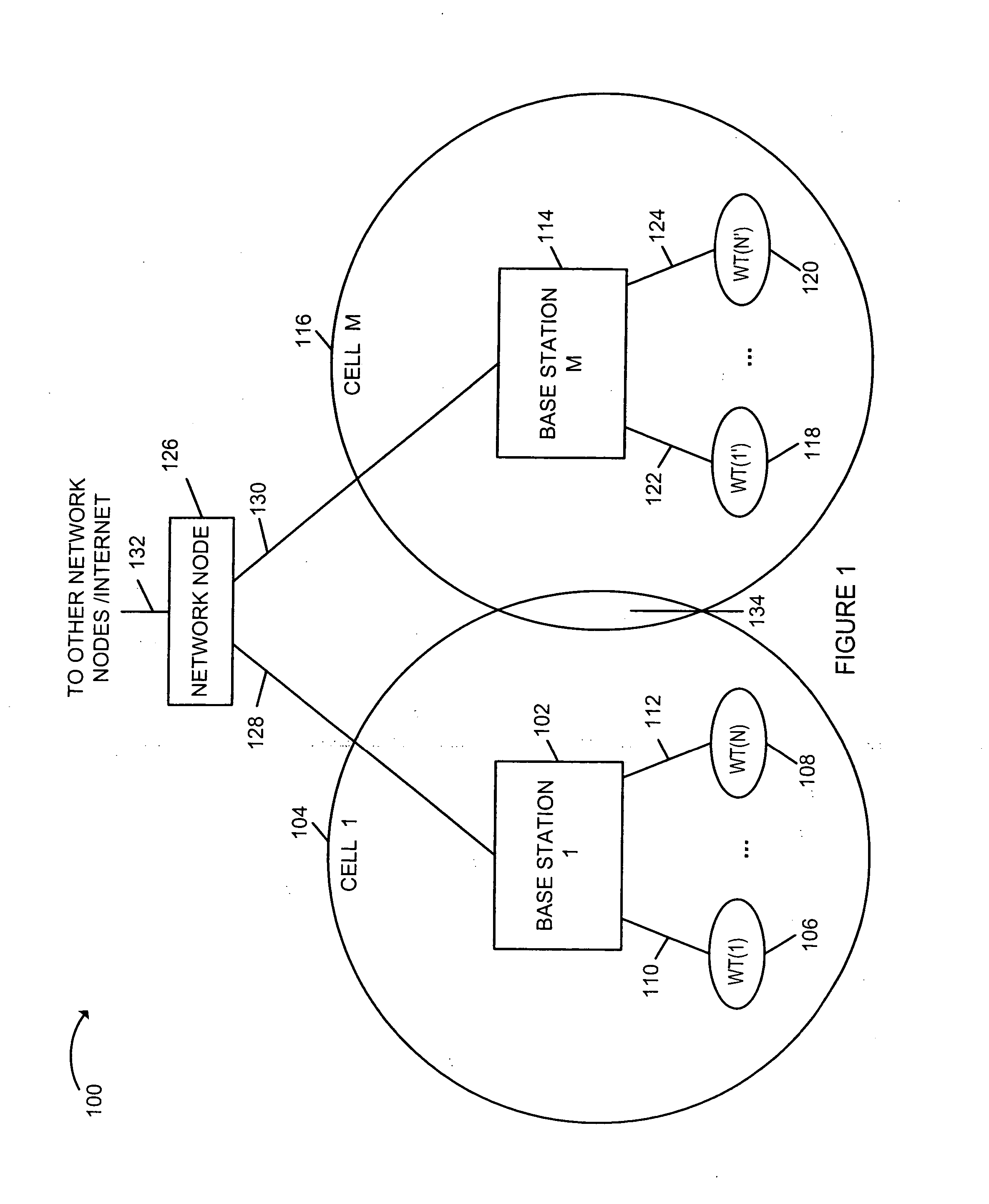
FIG. 1 is an illustration of an exemplary wireless communications system 100, implemented in accordance with the present invention. Exemplary wireless communications system 100 includes a plurality of base stations (BSs): base station 1102, base station M 114. Cell 1104 is the wireless coverage area for base station 1102. BS 1102 communicates with a plurality of wireless terminals (WTs): WT(1) 106, WT(N) 108 located within cell 1104. WT(1) 106, WT(N) 108 are coupled to BS 1102 via wireless links 110, 112, respectively. Similarly, Cell M 116 is the wireless coverage area for base station M 114. BS M 114 communicates with a plurality of wireless terminals (WTs): WT(1′) 118, WT(N′) 120 located within cell M 116. WT(1′) 118, WT(N′) 120 are coupled to BS M 114 via wireless links 122, 124, respectively. WTs (106, 108, 118, 120) may be mobile and / or stationary wireless communication devices. Mobile WTs, sometimes referred to as mobile nodes (MNs), may move throughout the system 100 and may...


PUM


Abstract

Methods and apparatus for providing channel diversity to wireless terminals (WTs) in a manner that reduces the latency between the time a WT encounters satisfactory channel conditions are described. A plurality of communications channels with different physical characteristics are maintained in a cell by a base station (BS). Each WT monitors multiple channels and maintains multiple channel estimates at the same time so that rapid switching between channels is possible. Channel quality information is conveyed from each WT to the BS. The WT or BS selects a channel based on the measured channel quality. By supporting multiple channels and by introducing periodic variations into the channels in various embodiments, the time before a WT encounters a channel with good or acceptable channel conditions is minimized even if the WT does not change location. Multiple antennas are used at the BS to support numerous channels simultaneously, e.g., by controlling antenna patterns.

Description

FIELD OF THE INVENTION The present invention relates to communications systems and, more particularly, to methods and apparatus for providing transmit diversity in a multiple access cellular communications network. BACKGROUND In a wireless communication system, a base station, situated at a fixed location, communicates with a plurality of wireless terminals, e.g., mobile nodes that may move throughout its cell. A given base station, with a single fixed antenna may have a fixed antenna pattern. Consider a single base station; its antenna pattern will support variable levels of channel quality between the base station and mobile nodes, depending on the mobile node's location with respect to the antenna pattern. Now consider that an adjacent base station, with its own antenna pattern, may be creating different levels of interference at different locations. The channel quality between the base station and a mobile node will vary as the mobile node moves to different locations within t...

Claims


Application Information

Patent Timeline
Patent Type & Authority Applications(United States)
IPC IPC(8): H04B7/06H04W88/18
CPCH04B7/0626
Inventor LAROIA, RAJIVLI, JUNYIRANGAN, SUNDEEPSRINIVASAN, MURARI
Owner QUALCOMM INC
Why Eureka
Try Eureka