Grid for guided operations

a guided operation and grid technology, applied in the field of grid guided operations, can solve the problems of grid not being designed to be removable and repositionable, and the construction of the ct guide did not allow the removal of the grid over an instrument, and achieve the effect of extending the width

Inactive Publication Date: 2005-01-06
APRIOMED
View PDF17 Cites 22 Cited by
  • Summary
  • Abstract
  • Description
  • Claims
  • Application Information

AI Technical Summary

Benefits of technology

[0005] One object of the present invention is to provide an improved grid comprising a flat frame provided with transverse ribs or bars, the improvement being that the transverse ribs are elastic such that two adjacent ribs can be stretched and separated from each other. An opening is thereby created, by which the grid can be threaded over a biopsy instrument introduced between the two ribs. With a grid having elastic ribs, it is also possible to palpate the area below the grid without removing the grid, something that can be of considerable advantage when the grid is attached to a patient's skin by, for example, adhesive tape or adhesive provided at the underside of the grid.
[0006] Furthermore, when determining between which two grid ribs a percutaneous operation is to be performed, a doctor must decide if the respective ordinal number of a rib is counted from the left or right side of the grid. A grid should therefore preferably be equipped with some kind of markings that enable a doctor to unambiguously distinguish the right side of the grid from the left side. A distinguishing feature of this kind is even more valuable when the grid is a removable and repositionable grid—as provided by the present invention—because the risk of accidentally rotating the grid 180° during repositioning of the grid should be eliminated. In one embodiment of the present invention, one of the sides of the grid frame is therefore provided with an enlarged width in comparison with the opposite side, whereby the risk of accidentally rotating the grid 180° is avoided.

Problems solved by technology

The construction of this CT guide did not allow for the removal of the grid over an instrument, such as a biopsy needle, introduced in a patient's body.
Consequently, the grid was not designed to be removable and repositionable.

Method used


Image

  • Grid for guided operations
  • Grid for guided operations

Examples


Embodiment Construction

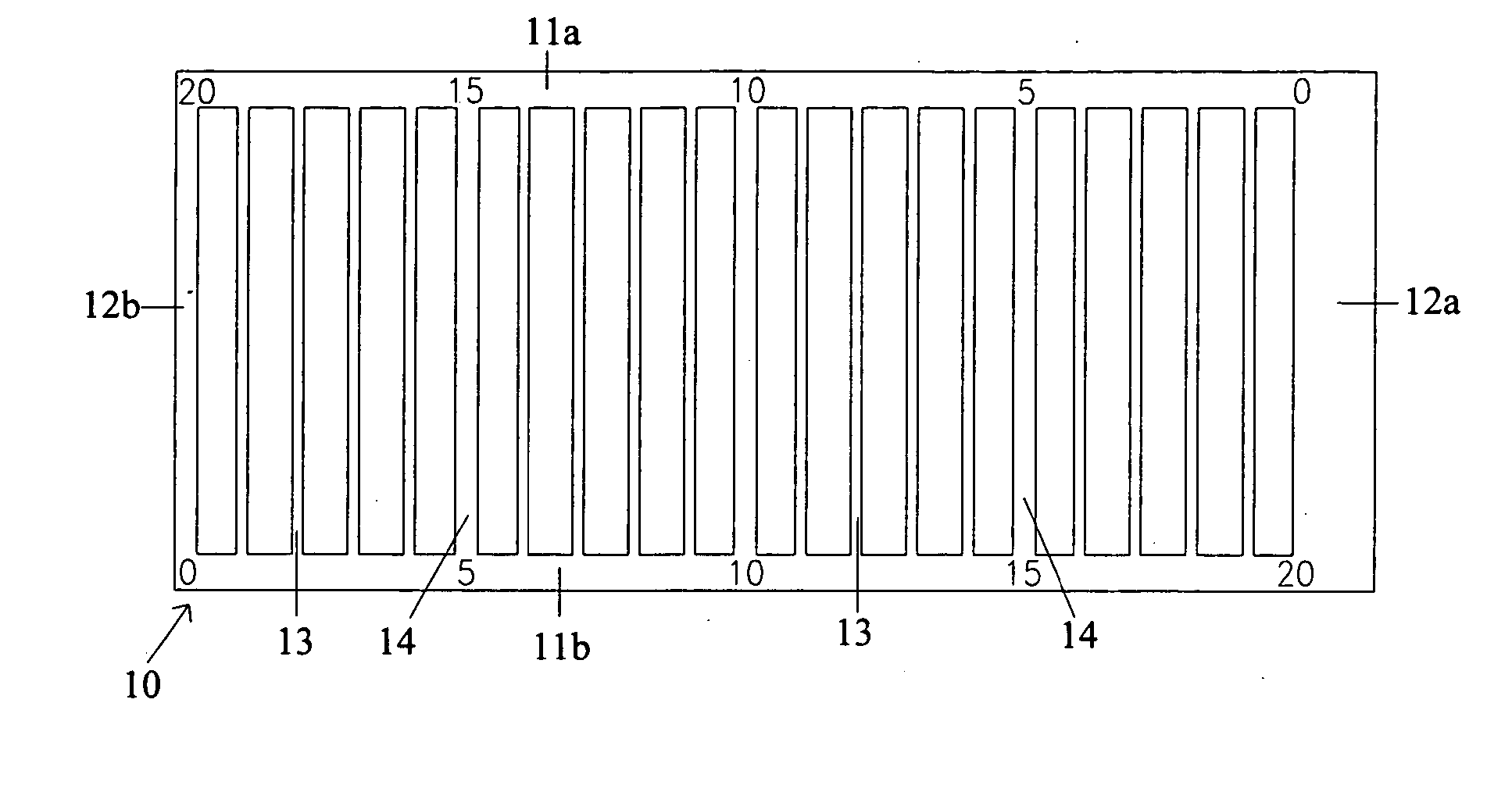
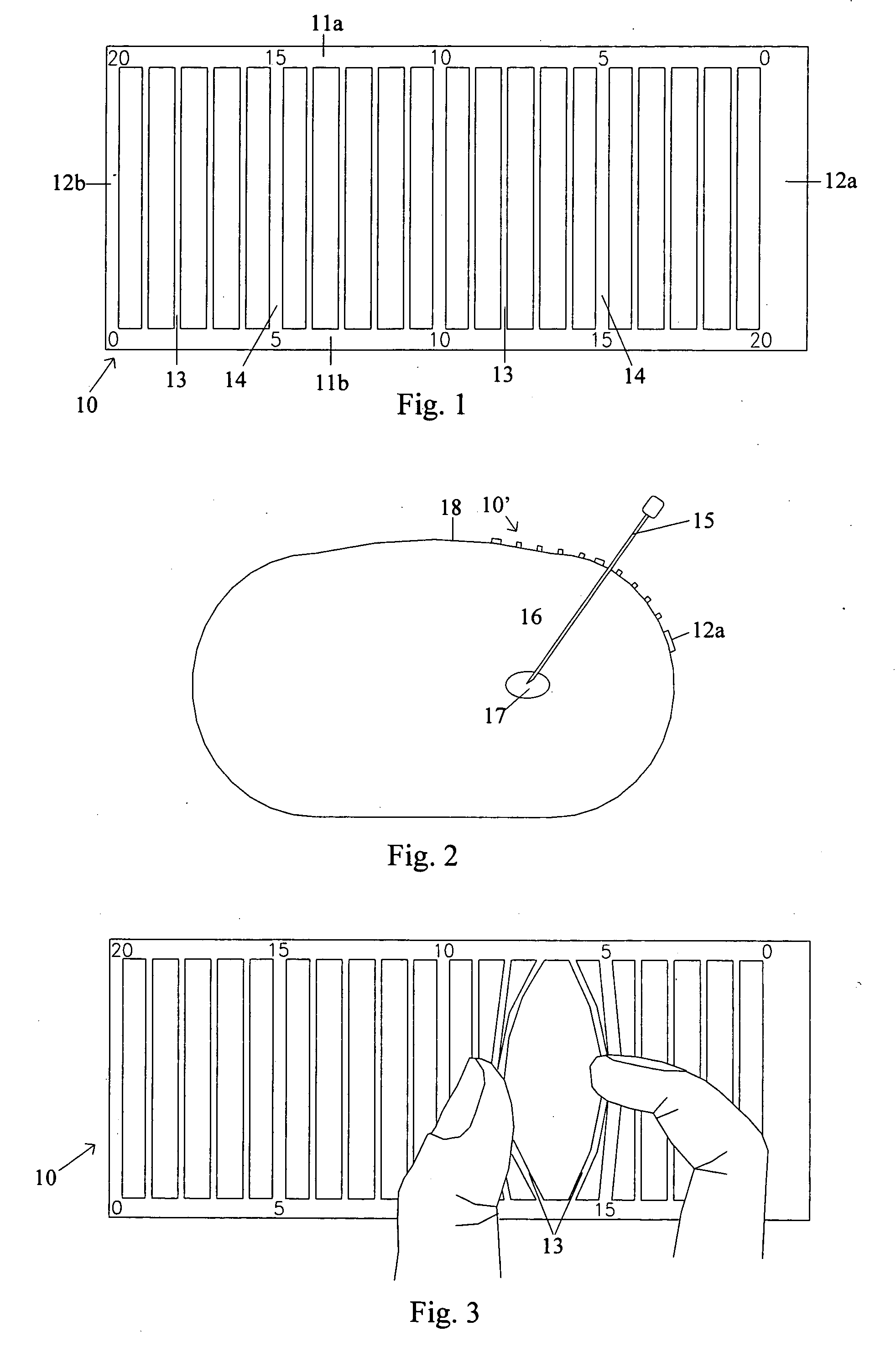
[0010] In FIG. 1, a grid 10 according to the present invention is illustrated. The grid 10 comprises a generally flat and rectangular frame having two long sides 11a, 11b and two short sides 12a, 12b. Several transverse bars or ribs 13, 14 are connected to the long sides 11a, 11b. To strengthen the frame and to facilitate the determination of between which of the ribs a puncture is to be performed, some of the ribs have been given a larger width than the other ribs. As can be seen from FIG. 1, each fifth rib is broader than the intermediate ribs. These broader ribs have been marked with reference numeral 14, and the frame is also provided with numbers (in this example, 0, 5, 10 and 20) that represent the ordinal number of the respective rib. It should further be noted that one of the short sides (short side 12a in FIG. 1) has been given a larger width than the opposite short side 12b. The purpose and advantage of the latter feature will become apparent from the description below.

[0...


PUM


Abstract

The invention relates to a grid (10) adapted to be arranged on a patient's skin to provide positioning information in CT-guided percutaneous operations. In one embodiment, the grid (10) comprises a flat and generally rectangular frame having two long sides (11a, 11b) and two short sides (12a, 12b), with a number of transverse ribs (13, 14) being provided between the two long sides (11a, 11b). According to the invention, at least some of the transverse ribs (13, 14) are elastic. By using his/her fingers, a doctor can thereby separate two neighbouring ribs (13, 14) such that an opening is provided in the grid (10). Through this opening access is obtained to the skin area under the grid (10), or the grid (10) can be threaded over and removed from a medical instrument which, between two adjacent ribs (13, 14), is inserted into the patient's body.

Description

FIELD OF THE INVENTION [0001] The present invention relates generally to a medical guidance device for use in guided medical operations (for example, CT-guided operations), and in particular to a grid with which the correct entrance position for a biopsy instrument can be determined during a CT-guided biopsy operation. BACKGROUND OF THE INVENTION [0002] In a medical operation involving the percutaneous insertion of an elongated instrument to a predetermined position within a patient's body, the direction and the insertion depth as well as the entrance position at the patient's skin have to be determined. When the medical operation in question is a biopsy operation performed by means of computerized tomography (CT), the direction and the insertion depth can be calculated from coordinates given on a CT screen. Regarding the entrance position, a CT scanner provides information about where a particular picture of a slice has been taken, i.e. the position along the length of a patient's ...

Claims


Application Information

Patent Timeline
Patent Type & Authority Applications(United States)
IPC IPC(8): A61B10/02A61B6/03A61B6/12A61B19/00A61M5/42
CPCA61B19/201A61B19/54A61B2019/5437A61B6/037A61B2019/547A61M5/427A61B2019/5454A61B90/11A61B90/39A61B2090/3937A61B2090/3954A61B2090/397
Inventor ASTROM, GUNNAR
Owner APRIOMED
Why Eureka
Try Eureka