Robot off-line simulation apparatus

a simulation apparatus and robot technology, applied in computer control, program control, instruments, etc., can solve the problems of inability to operate at the determined placing position, difficult to make the on-screen positional relationship between the robot and the peripheral device perfectly correspond, and inability to optimize the determined positioning position. to achieve the effect of reducing cost and tim

Active Publication Date: 2005-01-06
FANUC LTD
View PDF7 Cites 31 Cited by
  • Summary
  • Abstract
  • Description
  • Claims
  • Application Information

AI Technical Summary

Benefits of technology

The present invention enables to determine a robot placing position where that the robot is operable at all the task points or over the entire operation path and also the robot does not interfere with the workpiece or the peripheral device in a short time, to expedite a review of the arrangement of the robot system. Further, a person can know how large a margin is left for discrepancy between a placement assumed on the basis of off-line data and a real placement, before going to an actual working site. Hence, placement of the robot on the actual working site is easy to perform, and even an unskilled person can think about a more appropriate way of applying the robot.
Specifically, the present invention makes it possible not only to check in advance whether the robot placing position is optimal or not but also to know how large a margin the placement has. Hence, it is no longer necessary to change the placing positions of the robot, workpiece and peripheral device after the system is actually built. This reduces the cost and time required for building the robot system.

Problems solved by technology

If the robot is placed at an inappropriate position, it causes problems such that a task point or a part of an operation path for the robot proves to be in a region where the robot cannot operate, or that the robot interferes with a peripheral device when the robot is made to operate on an intended sequence of task points or an intended operation path.
However, even when a robot system is built on the basis of a robot placing position determined to satisfy the conditions as mentioned above, it is not rare that problems occur such that the determined placing position is not optimal, so that the cycle time and duty of the robot exceed stipulated values.
Further, even when a robot placing position thought to produce good results is determined in the simulation system in the conventional manner described above, problems occur such that when the real robot is placed at the determined placing position on an actual working site, it turns out that the robot cannot operate at the determined placing position on the actual working site although on the screen, it appears to be able to operate.
Hence, the robot placement needs to be changed on the working site, which is very inefficient.
This comes from the fact that it is actually very difficult to make the on-screen positional relationship between the robot and the peripheral device perfectly correspond to the real positional relationship between them.
As mentioned above, there are following problems: Even if a robot placing position thought to ensure that the robot will be able to operate at all the task points or over the entire operation path and that the robot will not interfere with the peripheral device is obtained on the robot off-line programming system, it is not sufficient.
Further, the robot placement needs to be reviewed and changed when it causes trouble in the robot operation.
As a result, unexpected time and cost is required to build the robot system.
Conventionally, there is no way to check whether the off-line determined robot placing position is optimal or not.
Thus, the placing positions for the robot, the workpiece and the peripheral device often need to be reviewed and changed, and hence, unexpected time and cost is required to build the robot system.
Further, with the technique disclosed in the above-mentioned publication, the problems due to the discrepancy between a placement on the screen and a placement on the actual working site cannot be solved, so that there is a high possibility that the placement needs to be changed on the actual working site.

Method used


Image

  • Robot off-line simulation apparatus
  • Robot off-line simulation apparatus
  • Robot off-line simulation apparatus

Examples


Embodiment Construction

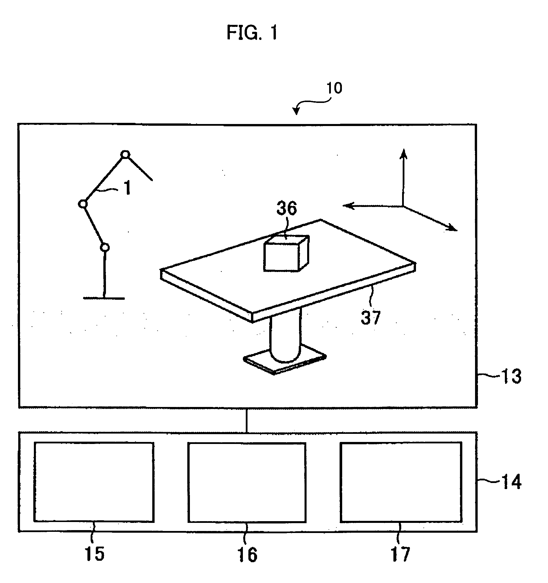
FIG. 1 is a block diagram showing an arrangement of parts of a robot off-line simulation apparatus 10 according to an embodiment of the invention. As shown in FIG. 1, the robot off-line simulation apparatus 10 as a whole comprises a display part with a screen 13 and a main part 14. The main part 14 includes an animation arithmetic display unit 15, a data storage unit 16, a robot operation / placement arithmetic unit 17.

Although not shown in the figure, a keyboard, a mouse and the like are attached to perform editing, correcting, feeding, etc. of program data, parameter data, instructions, etc. for these parts of the robot off-line simulation apparatus through manual operation, when necessary. Further, a main CPU not shown in the figure performs overall control on the individual parts of the simulation apparatus according to system programs, etc. stored in the data storage unit 16. Further, the simulation apparatus is arranged to be able to send and receive data to and from a CAD syst...


PUM


Abstract

A robot off-line simulation apparatus that allows a person to know an optimum placement for a robot, an operation margin index, etc. before going to an actual working site. Provisional robot placing positions are selected using data about a given sequence of task points (operation path), etc. The conditions for selection are (i) that solution to the inverse kinematics should be found regarding the entire sequence of task points, (ii) that the robot should not interfere with a peripheral device, and (iii) that regarding all the axes of the robot, the operation margin index should satisfy a criterion value. Simulation is performed according to operation programs under the condition that the robot is placed at each of the provisional placing positions, where data about cycle time, duty, energy value, change in acceleration/speed, etc. is collected. Using the collected data, evaluation of operation is performed regarding each of the provisional placing positions, and those provisional placing positions which allow good operation are identified as placing positions ensuring the robot operation. Further, using an evaluation function in which each aspect is given a weighting, the placing positions ensuring the robot operation are reduced to optimum placing positions ensuring the robot operation.

Description

BACKGROUND OF THE INVENTION 1. Field of the Invention The present invention relates to a robot off-line simulation apparatus for performing simulation of operation of a robot, more specifically a robot off-line simulation apparatus having a function of obtaining an optimum placement for a robot. 2. Description of Related Art A robot off-line simulation apparatus for performing off-line simulation of operation of a robot is known to the public. When simulation of operation of a robot is performed with this apparatus, generally the three-dimensional models of a robot, a workpiece, a peripheral device, etc. are placed and displayed -on a screen simultaneously. Obviously, the result of the simulation varies to a large degree depending on where the robot is placed on the screen (more precisely, in a space represented by the robot off-line simulation apparatus). If the robot is placed at an inappropriate position, it causes problems such that a task point or a part of an operation pat...

Claims


Application Information

Patent Timeline
Patent Type & Authority Applications(United States)
IPC IPC(8): B25J9/22B25J9/16G05B19/4069
CPCB25J9/1664B25J9/1671G05B2219/40629G05B2219/40465G05B2219/40515G05B2219/40317
Inventor WATANABE, ATSUSHINAGATSUKA, YOSHIHARUKOSAKA, TETSUYA
Owner FANUC LTD
Why Eureka
Try Eureka