Telescopic support tower

a technology of support towers and telescopic beams, which is applied in the direction of girders, machines/engines, mechanical equipment, etc., can solve the problems of high rental costs for heavy lifting cranes, increased material installation costs, and increased labor costs, so as to prevent sway and reduce the cost of erection. , the effect of preventing sway

Inactive Publication Date: 2005-01-13
ZTEK
View PDF34 Cites 52 Cited by
  • Summary
  • Abstract
  • Description
  • Claims
  • Application Information

AI Technical Summary

Benefits of technology

[0022] A further object of the present invention is to provide a support tower in accordance with the preceding objects in which the erection process can be safely and quickly performed by a small crew of personnel while maintaining complete stability of the tower sections during erection, with the elevating process being reversible in the event it is necessary to lower the load supported at the upper end of the tower for maintenance or replacement purposes.
[0023] Yet another object of the present invention is to provide a telescoping support tower for heavy wind turbines in which the telescoping tower sections are provided with guiding mechanisms to maintain the sections in alignment during lifting and lowering and to prevent sway that may be caused by high winds acting on the nacelle and turbine blades.
[0024] Still a further object of the present invention is to provide a support tower for supporting heavy structures at a high elevation in accordance with the preceding objec

Problems solved by technology

A problem existed, however, in that as the tower was tilted into vertical position, the feet of the tower conflicted with anchor bolts that protruded from the foundation which would prevent the tower from setting flat on the foundation.
However, as the tower height increased along with the generating capacity and the weight of the wind turbine generator, the costs of installation increased materially.
The transportation costs to move a heavy lift crane to a site of installation and then remove it from the site of installation, as well as the rental cost for a heavy lift crane, can be extremely high.
A typical heavy lift crane with a lifting capacity of approximately 230 tons is barely capable of installing a 750 kilowatt wind turbine generator on a tower that is about 200 feet tall.
Extra-heavy lift cranes with even higher costs are required for taller towers or heavier generators.
Use of the extra-heavy lift cranes increases costs dramatically due to the very high rental and transportation costs of these larger units.
Additional costs include the requirement for multiple large trucks and trailers for moving the extra-heavy lift crane to and from the job site, increased risk of serious accidents while traveling during movement of the crane to and from the job site, as well as at the job site, and increased wear and tear on public highways and plant site roads.
The massive size of extra-heavy lift cranes and their limited mobility require that work sites be well prepared to assure stability during the erection process.
Also, once on a job site, the cranes need to be moved frequently from one wind turbine foundation to another which further adds to high maintenance costs on the cranes and roads and expensive time-consuming moving procedures.
This is especially problematic at preferred and available job sites which are usually near the top of hills, ridges or mountains which require erection equipment to be highly mobile in order to minimize erection time and cost.
Use of the extra-heavy lift cranes means that many of the best sites cannot be used due to the exces

Method used


Image

  • Telescopic support tower
  • Telescopic support tower
  • Telescopic support tower

Examples


Embodiment Construction

[0035] Although a preferred embodiment and alternative lift mechanisms for vertically extending the tower are disclosed and explained in detail, it is to be understood that the embodiment and alternatives are given by way of illustration only. It is not intended that the invention be limited in its scope to the details or sequence of construction and arrangement of components set forth in the following description or illustrated in the drawings. Also, in describing the preferred embodiment specific terminology will be utilized for the sake of clarity. It is to be understood that each specific term includes all technical equivalents that operate in a similar manner to accomplish a similar purpose.

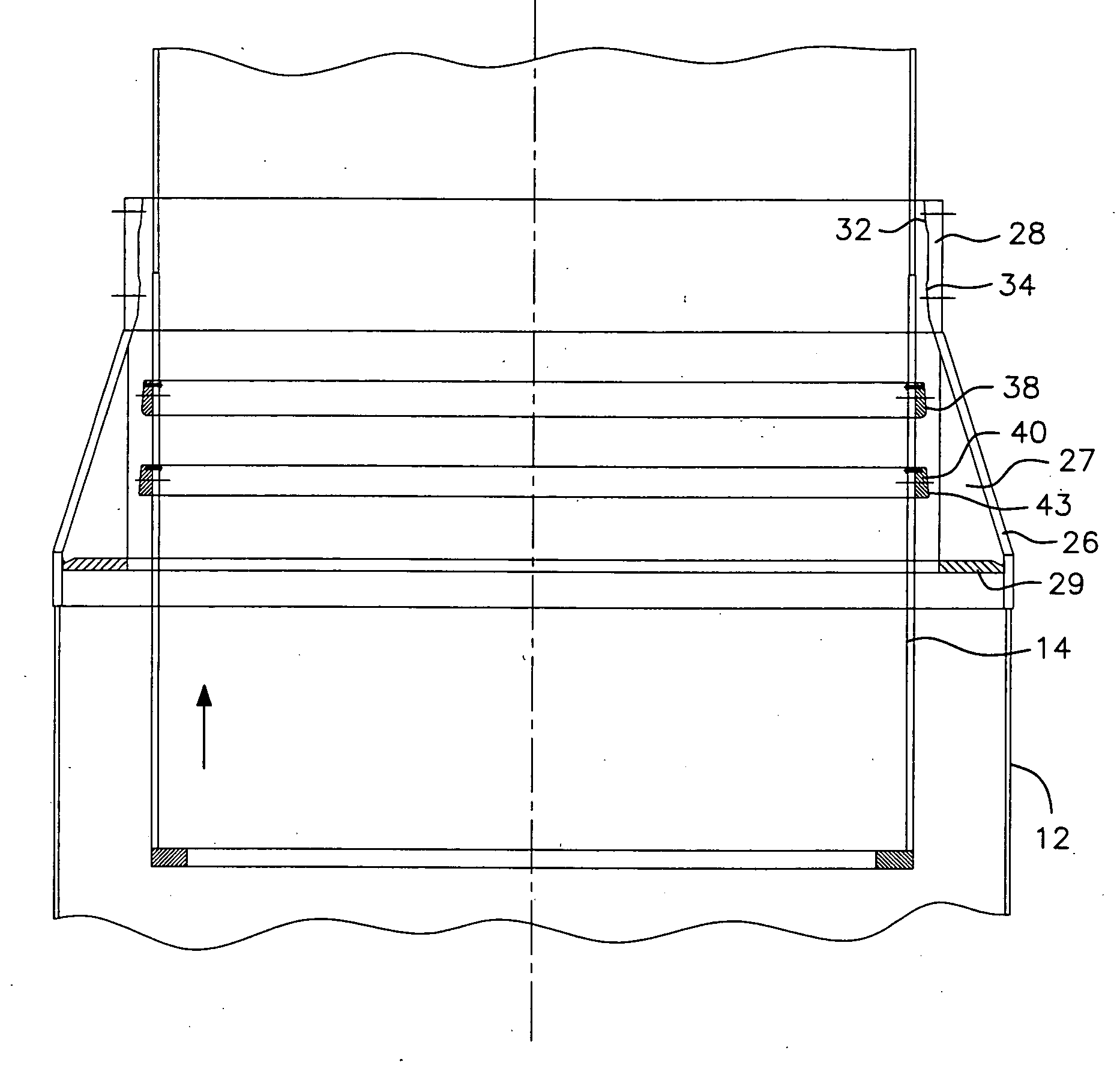
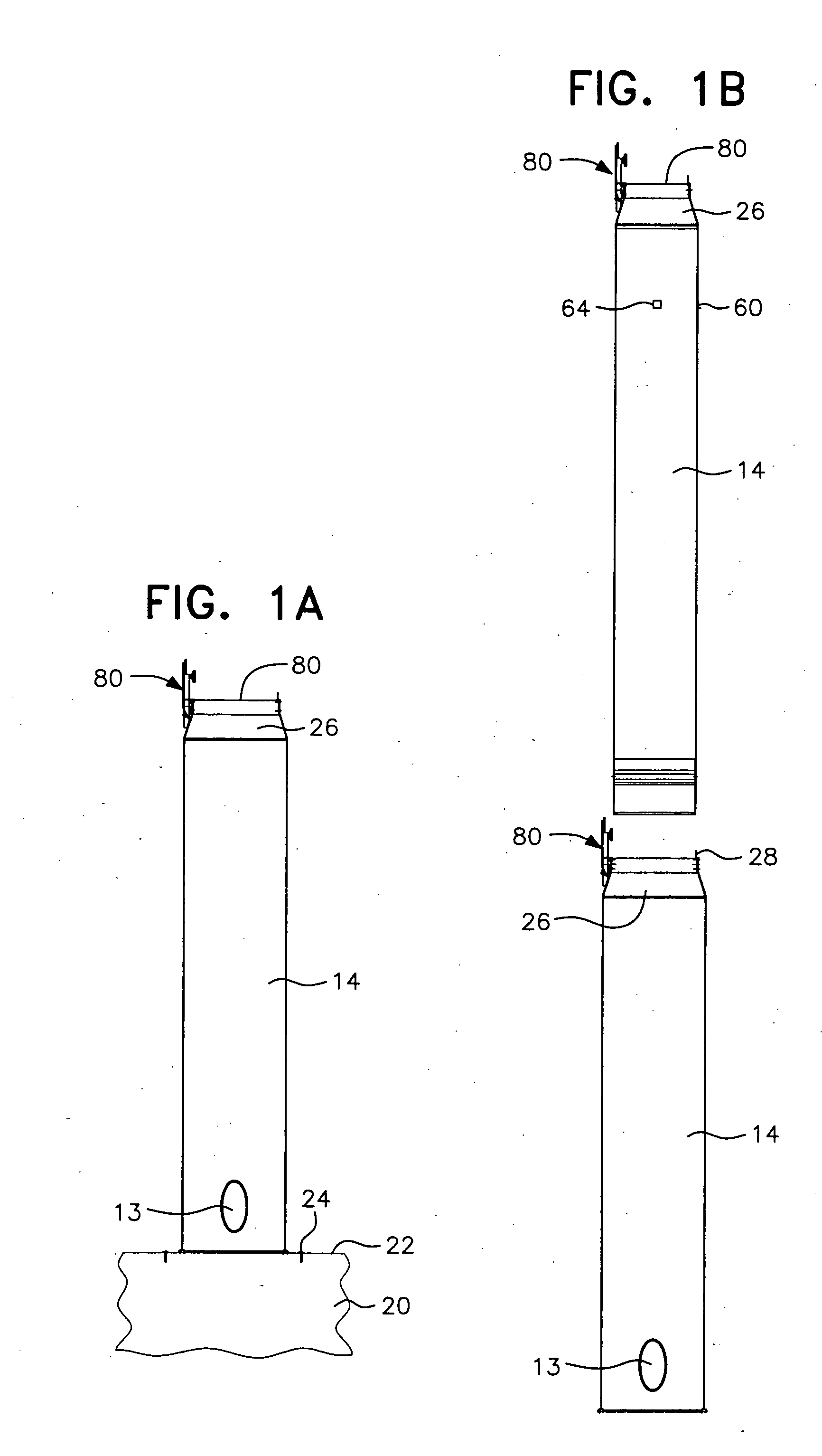
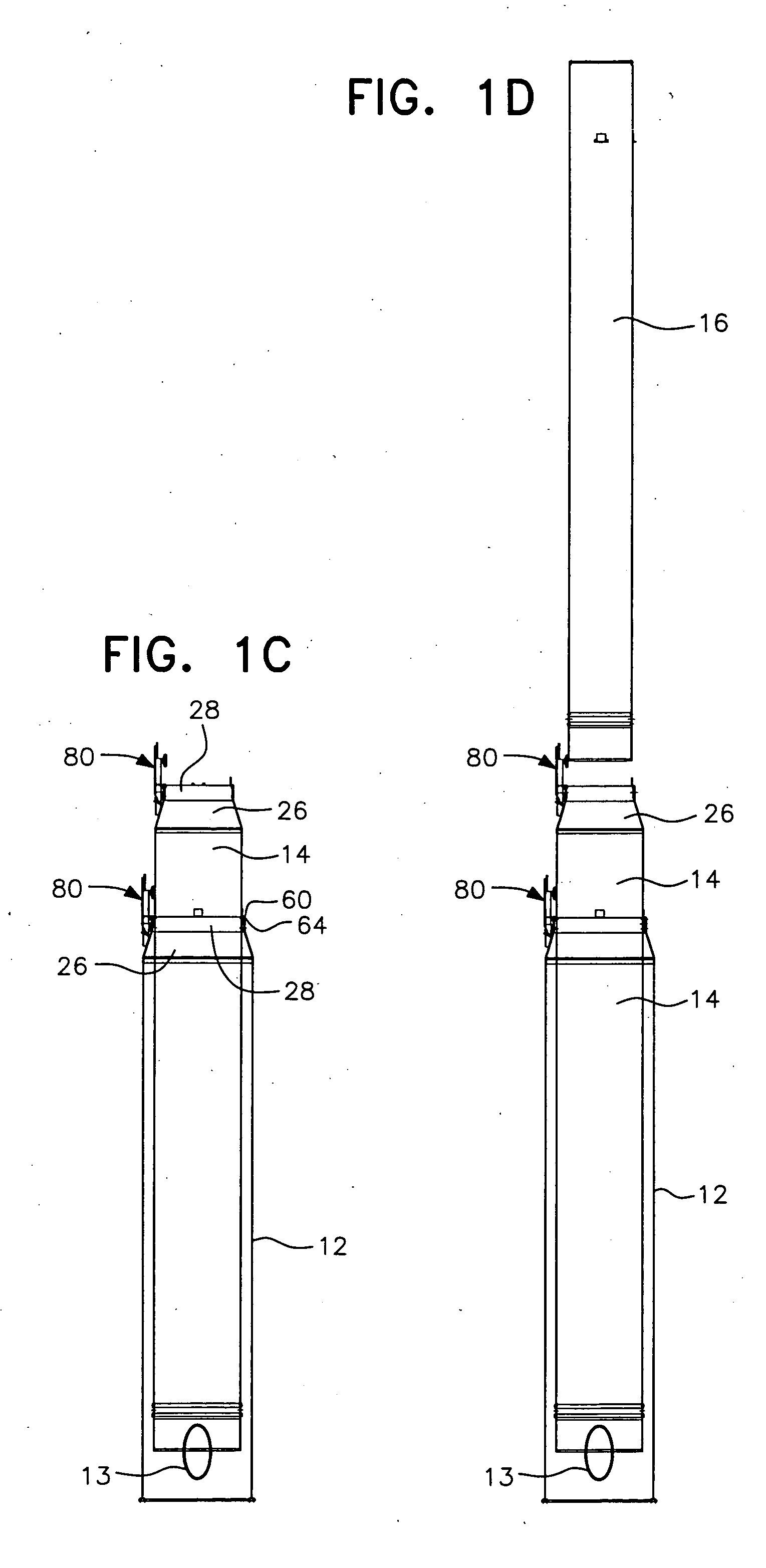
[0036] Referring to FIGS. 1A-1F of the drawings, an extended sectional telescopic tower and turbine generator assembly is illustrated in FIG. 1F and generally designated by reference numeral 10. FIGS. 1A-1F illustrate schematically the steps in assembling three tower sections 12, 14, and 16...


PUM


Abstract

A support tower for heavy loads or large structures such as a wind turbine generators, constructed of a plurality of telescopic tower sections with the outer lower tower section having a lower end supported from a foundation and at least one or more inner upper tower sections telescoped in an initial vertical nested relation within the outer lower tower section. The heavy load is mounted on an upper end of the inner upper tower section while in the initial vertical nested relation. The inner upper tower section or sections are then lifted upwardly to an extended tower height by lift mechanisms and the tower sections are secured in vertically extended position by inter-engaging wedge joint structure with bolt fasteners extending through mating wedge surfaces to retain the telescopic tower sections vertically extended and position the heavy load in a vertically elevated position.

Description

CROSS REFERENCE TO RELATED APPLICATION: [0001] This application is a continuation-in-part of pending U.S. patent application Ser. No. 09 / 729,250, filed Dec. 5, 2000, entitled “Tilt-Up and Telescopic Support Tower for Large Structures”, the disclosure of which is incorporated by reference as if fully set forth herein.BACKGROUND OF THE INVENTION [0002] 1. Field of the Invention [0003] The present invention generally relates to tall support towers for large structures, such as wind turbine generators, microwave antennas or the like, and, more specifically, to tall support towers which are constructed of multiple telescopic sections that telescopically extend vertically to the tower's full height and / or to tall support towers which are telescopically and vertically nested at the site of installation in a generally vertical position, and then extended upwardly to a final extended position to form a support tower. [0004] 2. Description of the Prior Art [0005] Wind-powered windmills and tu...

Claims


Application Information

Patent Timeline
IPC IPC(8): E04H12/18E04H12/34F03D11/04
CPCE04H12/182E04H12/34F03D1/001Y02E10/728F05B2240/9151F05B2240/91521F03D11/04F03D13/20F03D13/10F03D13/40Y02E10/72
Inventor HENDERSON, ALLAN P.GERSHONY, ZVIJOHNSON, VAUGHNGODFREY, ROBERT E.
Owner ZTEK
Why Eureka
Try Eureka