Vertical airflow engine cooling system

a cooling system and vertical airflow technology, applied in the field of cooling systems, can solve the problems of large amount of mechanical engine power consumed in the driving of the fan, degrade vehicle performance and fuel economy, and high noise levels

Active Publication Date: 2005-01-13
DEERE & CO
View PDF20 Cites 30 Cited by
  • Summary
  • Abstract
  • Description
  • Claims
  • Application Information

AI Technical Summary

Benefits of technology

[0007] These and other objects are achieved by the present invention, wherein a cooling system is provided for a non-rail off-road vehicle having an engine with a horizontally oriented rotation axis and a hood covering the engine. The cooling system includes an engine cooling radiator positioned above the engine and between the engine and the hood and a fan unit with electric motor-driven fans blowing air upwardly through the radiator. The fan unit is positioned above the engine and between the engine and the radiator. An engine charge air cooler is also positioned above the engine and between the engine and the hood, and a charge air cooler fan unit has electric motor-driven fans which blow air upwardly through the cooler. The hood has a plurality of openings in an upper surface thereof through which passes air blown by the radiator fan unit and the charge air cooler fan unit. This cooling system blows heated cooling air vertically upwardly, thus preventing the heated cooling air from being drawn back into the intakes of the cooling system and preventing heated air from being blown onto the exterior of the vehicle cab.

Problems solved by technology

A large amount of mechanical engine power is consumed in driving the fan.
This degrades vehicle performance and fuel economy and results in high noise levels.
Such tractor cooling systems also take up a lot of space in areas that interfere with the operator's view in the forward direction.
Such cooling systems may also blow heated air back toward the cab, thus heating the cab substantially, and increasing the heat load on the cab cooling and air conditioning system.
However, in most off-road vehicles, such as agricultural tractors, there is insufficient fore-and-aft room for such an arrangement of components, and there has not previously been sufficient electrical power capacity to power electric motor-driven cooling fans.

Method used


Image

  • Vertical airflow engine cooling system
  • Vertical airflow engine cooling system
  • Vertical airflow engine cooling system

Examples


Embodiment Construction

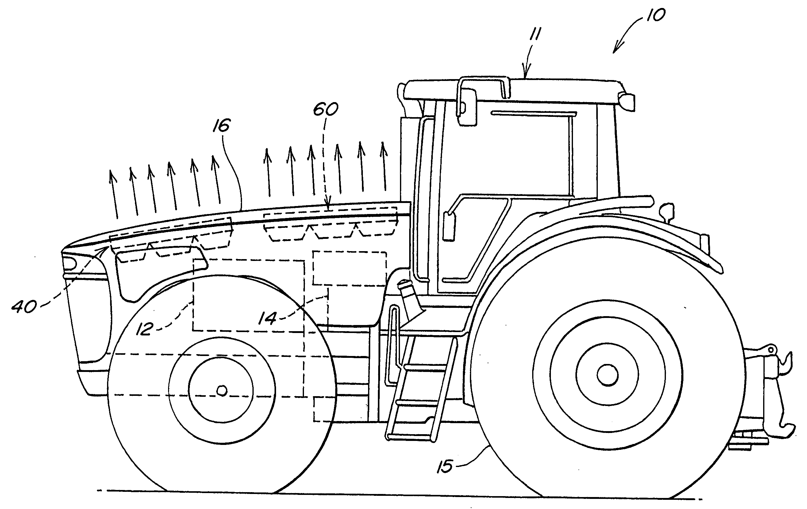
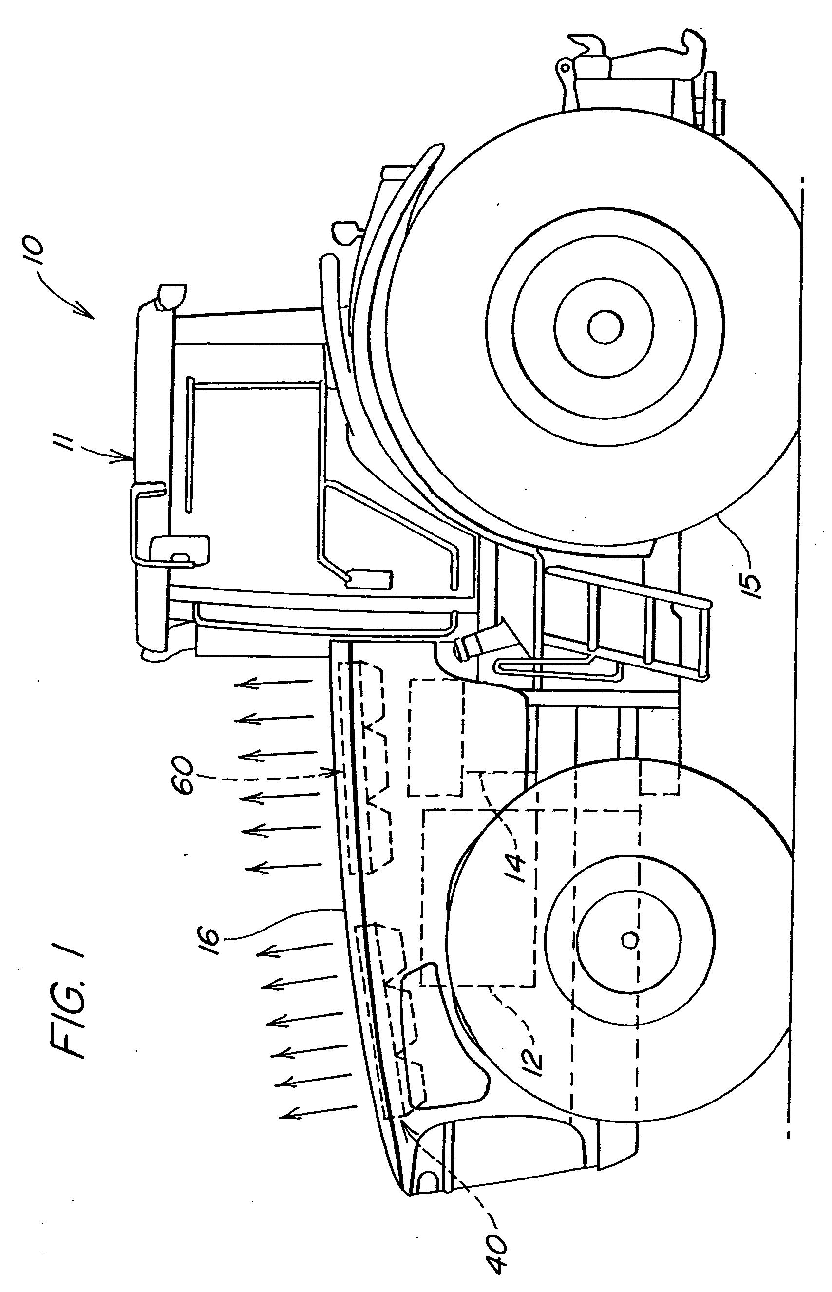
[0014] Referring to FIG. 1, a steerable, non-rail, off-road vehicle 10 (such as an agricultural tractor) includes a cab 11, an internal combustion engine 12, a transmission 14 for mechanically driving wheels 15, and a hood 16. Mounted under the hood 16 and above the engine 12 is an engine cooling radiator 40 and a charge air cooling unit 60.

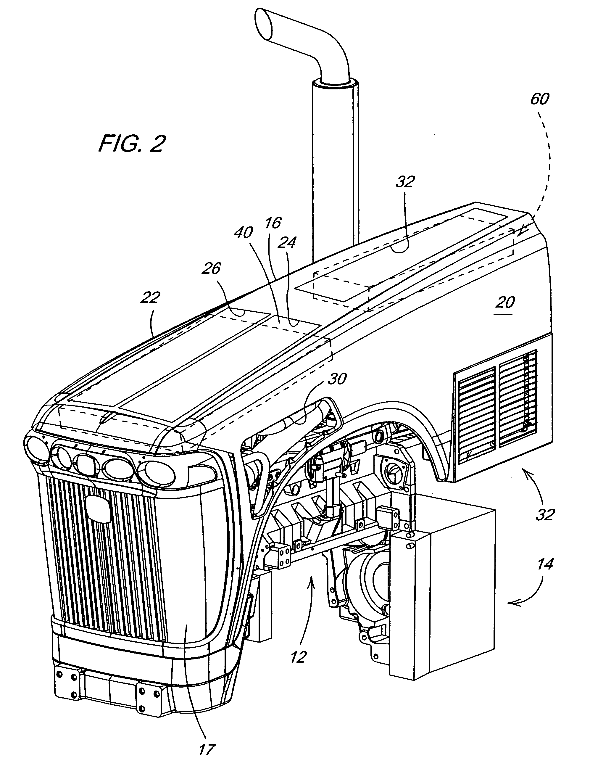
[0015] Referring to FIG. 2, a front grill 17 is at the front of the hood 16. The hood 16 has an upper panel 18 and left and right side panels 20, 22 (of which substantially only panel 20 is visible in FIG. 2). Upper panel 18 includes a pair of front openings 24, 26 and a rear opening 28. Side panel 20 includes a forward inlet opening 30, a rear inlet opening 32 and a wheel / axle recess 34. The engine 12 includes a turbo-compressor 33 which receives intake air from air cleaner 35.

[0016] As best seen in FIGS. 3, 4 and 5, the engine 12 includes an internal combustion unit 12A and accessories 12B. The engine cooling radiator 40 is mounted above engi...


PUM


Abstract

A cooling system is provided for a non-rail off-road vehicle, such as an agricultural tractor having an engine with a horizontally oriented rotation axis and a hood covering the engine. The cooling system includes an engine cooling radiator positioned above the engine and between the engine and the hood and a fan unit with electric motor-driven fans blowing air upwardly through the radiator. The fan unit is positioned above the engine and between the engine and the radiator. An engine charge air cooler is also positioned above the engine and between the engine and the hood, and a charge air cooler fan unit has electric motor-driven fans which blow air upwardly through the cooler. The hood has openings in its upper surface through which passes air blown by the radiator fan unit and the charge air cooler fan unit. This cooling system blows heated cooling air vertically upwardly, thus preventing the heated cooling air from being drawn back into the intakes of the cooling system and preventing heated air from being blown onto the exterior of the tractor cab.

Description

BACKGROUND [0001] The present invention relates to a cooling system for an engine powered non-rail off-road work vehicle such as an agricultural tractor. [0002] Current tractor cooling systems have components, such as a fan and a water pump which are mechanically driven by the engine. The mechanical drive limits the location of such components to on or near a rotation axis and at the front of the engine. A large amount of mechanical engine power is consumed in driving the fan. This degrades vehicle performance and fuel economy and results in high noise levels. Such tractor cooling systems also take up a lot of space in areas that interfere with the operator's view in the forward direction. Such cooling systems may also blow heated air back toward the cab, thus heating the cab substantially, and increasing the heat load on the cab cooling and air conditioning system. In certain conditions, such as a tail wind, the hot air blown by such cooling systems may, instead of exiting the regi...

Claims


Application Information

Patent Timeline
Patent Type & Authority Applications(United States)
IPC IPC(8): B60K11/04F01P1/00F01P3/04F01P3/18F01P5/02F01P5/04F01P5/06F01P7/16F02B63/04
CPCB60K11/04F01P3/18F01P2001/005F01P2003/185F02B63/04F01P2005/046F01P2060/02F01P2070/52F01P2005/025B60Y2200/221
Inventor VUK, CARL THOMAS
Owner DEERE & CO
Why Eureka
Try Eureka