Circular superdirective receive antenna arrays

a superdirective and antenna array technology, applied in direction finders using radio waves, polarised antenna unit combinations, instruments, etc., can solve the problems of low efficiency of these arrays, large antenna size needed for high gain and/or efficiency, and low efficiency of mf/hf/vhf systems

Inactive Publication Date: 2005-01-13
CODAR OCEAN SENSORS LTD
View PDF2 Cites 259 Cited by
  • Summary
  • Abstract
  • Description
  • Claims
  • Application Information

AI Technical Summary

Benefits of technology

According to yet another aspect of the invention, an apparatus for an antenna system includes a plurality of dipole elements located in a circular arrangement of a radius that is less than a detected wavelength to receive a plurality of analog signals, an analog-to-digital converter to convert the plurality of analog signals to a plurality of d...

Problems solved by technology
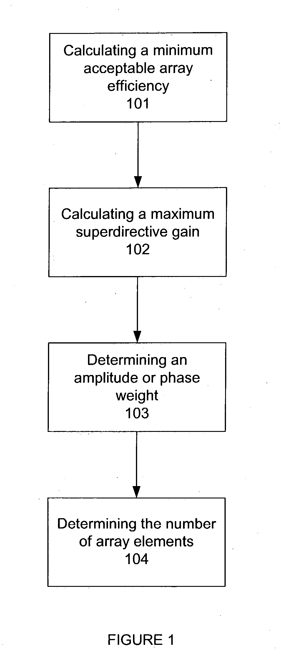
The drawback of MF/HF/VHF systems is the large antenna size needed for high gain and/or efficiency.
However, the efficiency of these arrays is low.
Thus, while the directive gain is high, the power gain is low.
This has been the primary source of criticism and lack of acceptance of superdirective arrays in practice.
These very intense echoes destroy the ability to see surface targets at the same ranges as the layer heights.
Although many receive antenna systems employ vertical dipole or monopole antennas that theoretically have an overhead null, in practice this is not nearly enough to eliminate all vestiges of the intense overhead echo.
Another und...

Method used


Image

  • Circular superdirective receive antenna arrays
  • Circular superdirective receive antenna arrays
  • Circular superdirective receive antenna arrays

Examples


Embodiment Construction

The invention and the various features and advantageous details thereof are explained more fully with reference to the nonlimiting embodiments that are illustrated in the accompanying drawings and detailed in the following description. Various substitutions, modifications, additions and / or rearrangements within the spirit and / or scope of the underlying inventive concept will become apparent to those of ordinary skill in the art from this disclosure.

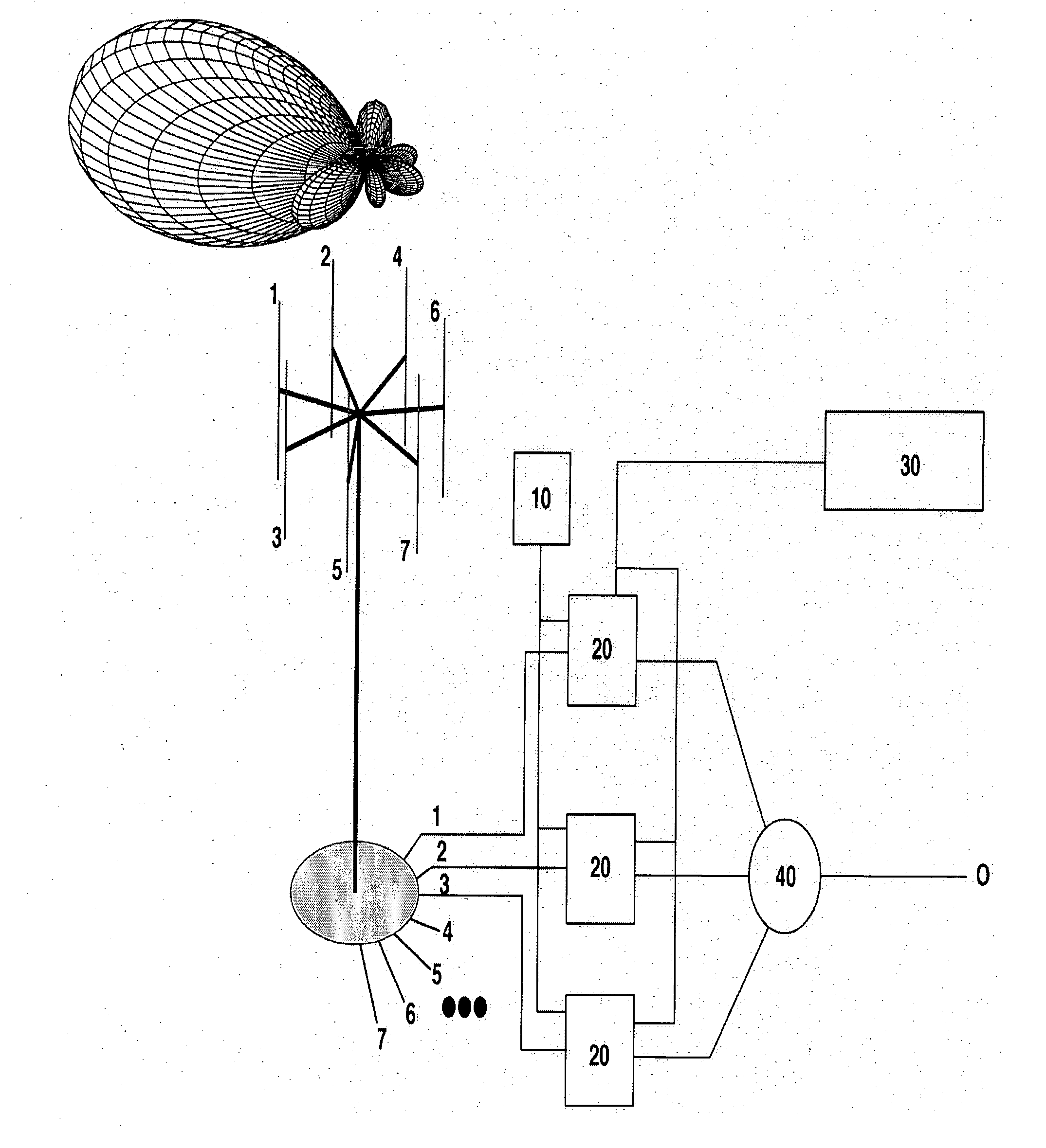
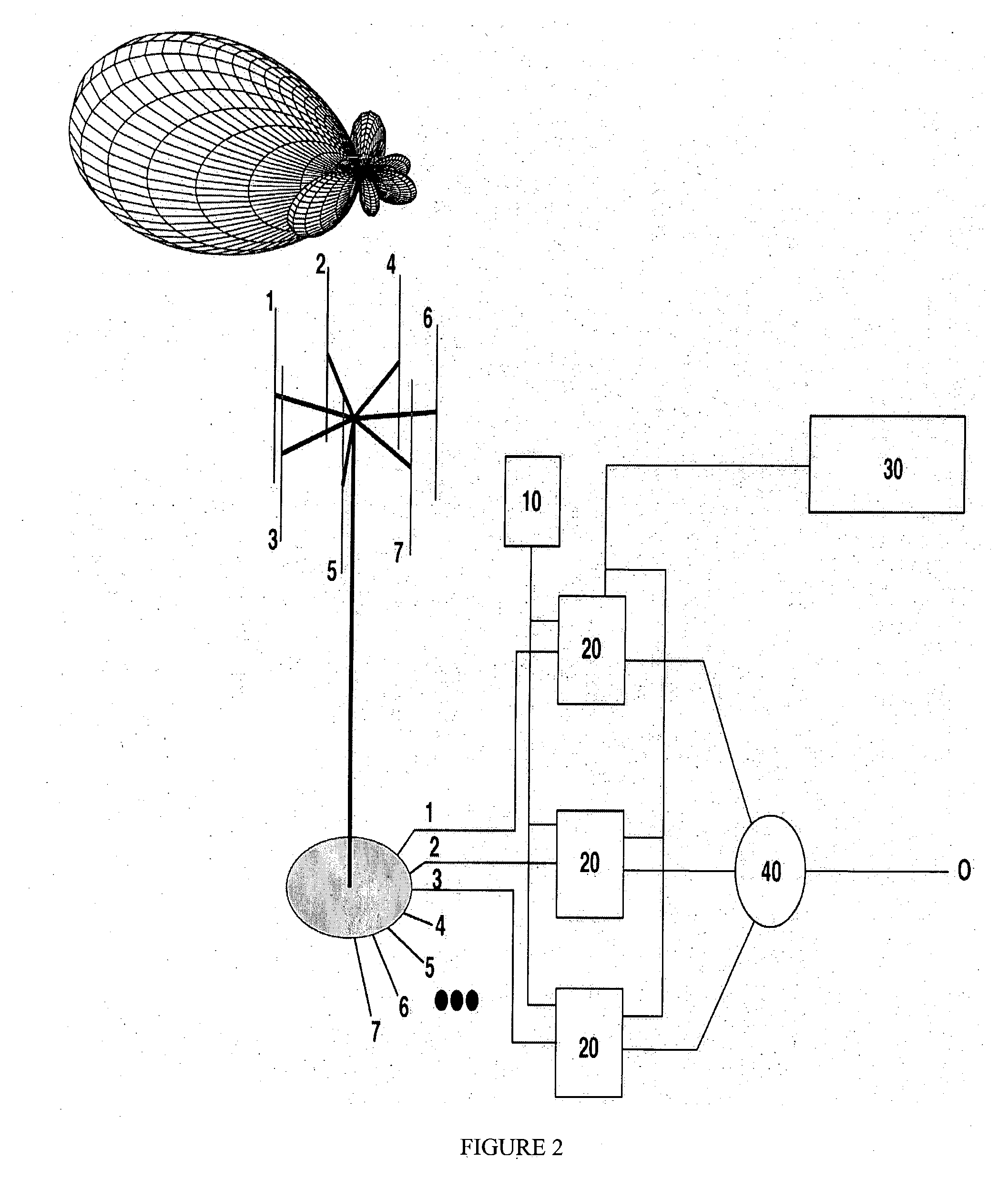
Techniques of the present disclosure can include providing a compact, circular array of antenna elements that realizes any directive gain.

Techniques of the present disclosure can also include maximizing compaction of an antenna array while maintaining the same signal-to-noise ratio.

Phasing schemes like the ones disclosed here supply additional overhead nulling while offering minimal to no sensitivity penalty to desired signals from elsewhere. In this sense, it can be considered an improvement to the superdirective class of arrays d...


PUM


Abstract

Systems and methods are described for circular superdirective receive antenna arrays. A method includes calculating an minimum array efficiency of the superdirective circular receive array, calculating a maximum superdirective gain of the superdirective circular receive array, determining an amplitude weight or a phase weight for an array element in the superdirective circular receive array based on the minimum array efficiency and the maximum superdirective gain, and determining number of array elements in the superdirective circular receive array and a radius of the superdirective circular receive array.

Description

BACKGROUND OF THE INVENTION 1. Field of the Invention The invention relates generally to the field of radars. More particularly, the invention relates to radar receive antenna arrays. Specifically, a preferred implementation of the invention relates to an optimized design for radar receive antenna arrays. 2. Discussion of the Related Art MF (medium frequency) / HF (high frequency) / VHF (very high frequency) radars and radios remain in demand even with the advent of satellites that extend the range of communication to global scales. HF signals have the advantage of spanning distances beyond the horizon limits of UHF and higher-frequency signals. Two modes account for this. Reflection of HF signals from the ionosphere is called the skywave mode, and permits radio signals to traverse half way around the world. In the surface-wave mode, the spherical earth diffracts vertically polarized signals beyond the visible horizon—even in the absence of an atmosphere or ionosphere. For surface w...

Claims


Application Information

Patent Timeline
IPC IPC(8): G01S7/02G01S13/02H01Q3/26H01Q9/18H01Q21/06H01Q21/20
CPCG01S13/0218H01Q21/205H01Q21/06H01Q3/2605
Inventor BARRICK, DONALD E.LILLEBOE, PETER M.
Owner CODAR OCEAN SENSORS LTD
Why Eureka
Try Eureka