Tilt control method, program, recording medium, and optical disk drive

a control method and program technology, applied in the direction of digital signal error detection/correction, instruments, recording signal processing, etc., can solve the problems of wave aberration, the degradation of the form of the optical spot, the degradation of the output signals, etc., and the wave aberration resulting from the tilt will not be negligible, so as to achieve sufficient precision and stably perform the accessing of the optical disk

Inactive Publication Date: 2005-01-13
RICOH KK
View PDF23 Cites 7 Cited by
  • Summary
  • Abstract
  • Description
  • Claims
  • Application Information

AI Technical Summary

Benefits of technology

[0013] An object of the present invention is to provide an improved tilt control method in which the above-described problems are eliminated.
[0014] Another object of the present invention is to provide a tilt control method that can control the inclination of the objective lens to the optical disk with sufficient precision without causing the fall of performance.
[0015] Another object of the present invention is to provide a computer program product embodied to cause a computer to execute the tilt control method that can control the inclination of the objective lens to the optical disk with sufficient precision without causing the fall of performance.
[0016] Another object of the present invention is to provide an optical disk drive that can stably access the optical disk with good response and incorporates the tilt control method that can control the inclination of the objective lens to the optical disk with sufficient precision without causing the fall of performance.
[0023] According to the tilt control method of the present invention, it is effectively possible to correct the inclination of the objective lens to the optical disk with sufficient precision without causing the fall of performance. Moreover, according to the computer program product of the present invention for control of the optical disk drive, it is effectively possible to correct the inclination of the objective lens to the optical disk with sufficient precision without causing the fall of performance. Moreover, according to the optical disk drive of the present invention, it is possible to stably perform the accessing of the optical disk with good response.

Problems solved by technology

However, when there is a deviation (which is called the “tilt”) in the direction of the optical axis of the objective lens from the direction perpendicular to the recording surface, the wave aberration is caused by the tilt, and there is a possibility of causing the degradation of the form of the optical spot and the degradation of the signals including the reproduction information, the servo information, etc. which are outputted from the light-receiving element.
However, if the numerical aperture of the objective lens becomes large, the influence of the wave aberration resulting from the tilt will not be negligible, and there is a possibility that the measures adequate for correcting the tilt cannot be taken with the devices disclosed in Japanese Laid-Open Patent Application No. 2001-052362 and Japanese Laid-Open Patent Application No. 2002-025090.

Method used


Image

  • Tilt control method, program, recording medium, and optical disk drive
  • Tilt control method, program, recording medium, and optical disk drive
  • Tilt control method, program, recording medium, and optical disk drive

Examples


Embodiment Construction

[0045] A description will now be given of the preferred embodiments of the invention with reference to the accompanying drawings.

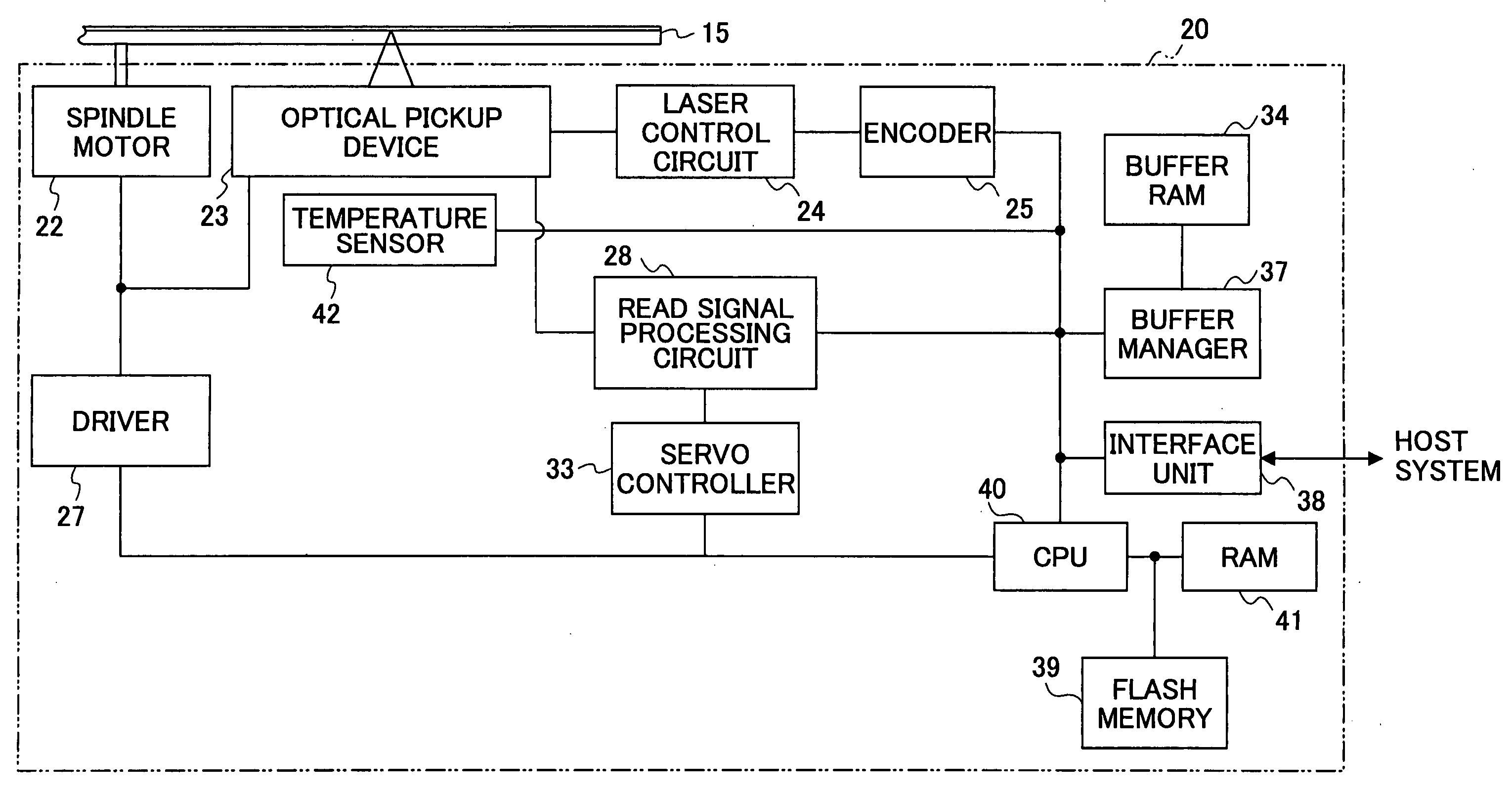
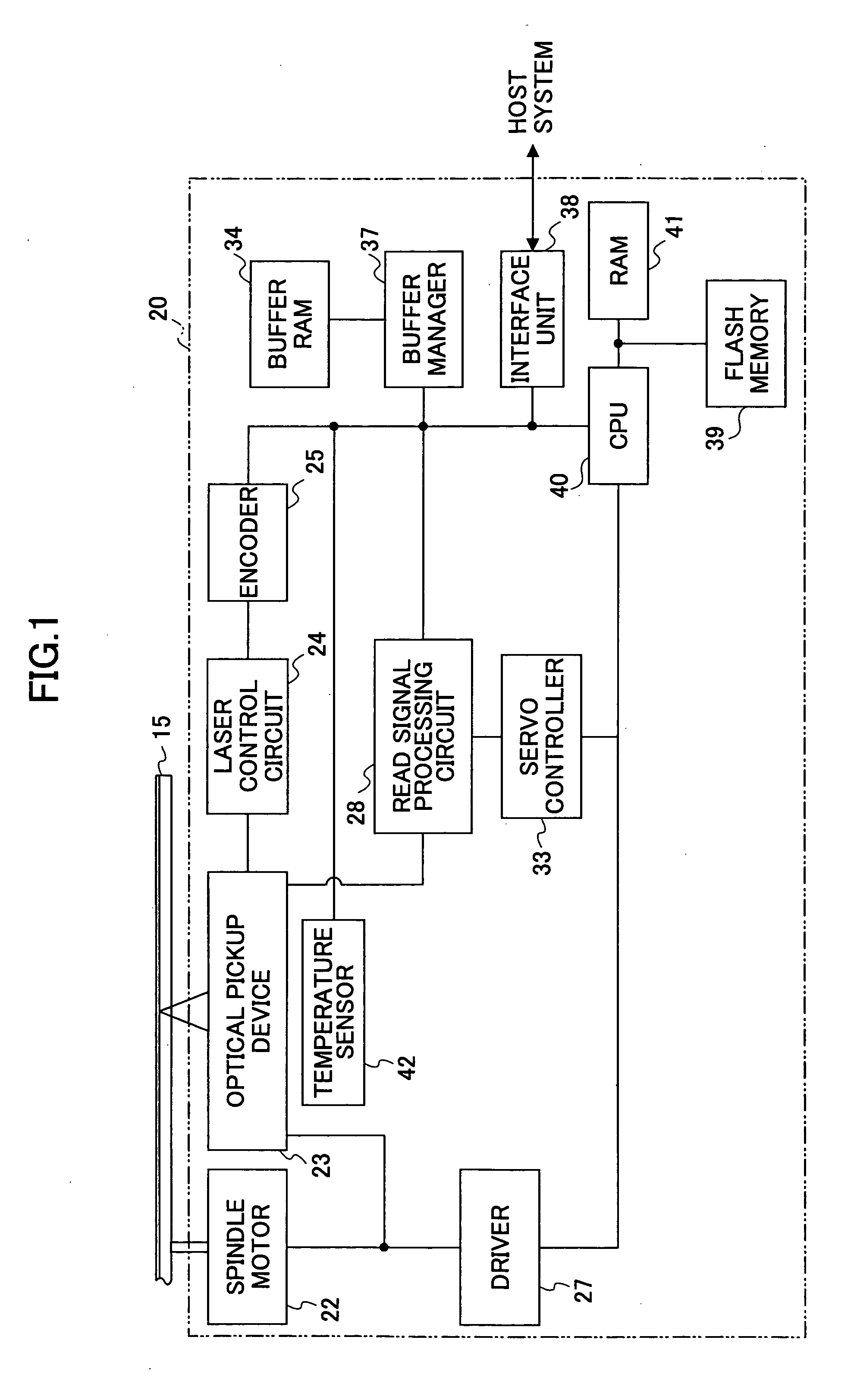
[0046]FIG. 1 shows the composition of the optical disk drive to which an embodiment of the present invention is applied.

[0047] As shown in FIG. 1, the optical disk drive 20 comprises the spindle motor 22 for carrying out the rotation drive of the optical disk 15, the optical pickup device 23, the laser control circuit 24, the encoder 25, the driver 27, the read signal processing circuit 28, the servo controller 33, the buffer RAM 34, the buffer manager 37, the interface unit 38, the flash memory 39, the CPU 40, the RAM 41 as the main memory, and the temperature sensor 42 as the temperature detection unit.

[0048] In addition, the connection line in FIG. 1 merely shows the typical signal or the typical information flow, but it does not express all the related connections of each block. Moreover, in the present embodiment, the optical disk based on the spec...


PUM

PropertyMeasurementUnit
wavelengthaaaaaaaaaa

Abstract

A tilt control method controls an inclination of an objective lens to an optical disk in which a track in the shape of a spiral or a concentric circle is formed. The tilt control method comprising steps of recording data to the optical disk, and acquiring, when recording the data to the optical disk, tilt control information for controlling the inclination of the objective lens based on both known compensation information that is defined with a plurality of kinds of signals acquired when reproducing data from a recorded region of the optical disk, and information that is related to an inclination of the objective lens when an amplitude of a tracking error signal is substantially a maximum in a recording region of the optical disk where the data are recorded.

Description

BACKGROUND OF THE INVENTION [0001] 1. Field of the Invention [0002] The present invention generally relates to a tilt control method, a program, a recording medium and an optical disk drive, and more specifically to a tilt control method which controls the inclination of the objective lens to the optical disk, a program of the tilt control method applied to the optical disk drive, a recording medium embodied therein to cause a computer to execute the tilt control method, and the optical disk drive which accesses the optical disk and incorporates the tilt control method. [0003] 2. Description of the Related Art [0004] With the improvement of the functions of personal computers, it has become possible for the computer to easily deal with the AV (audio-visual) information, such as music and images. Since the amount of the AV information is very large, the optical disks, such as CD (compact disc) and DVD (digital versatile disc), have come to attract the attention as an information reco...

Claims


Application Information

Patent Timeline
Patent Type & Authority Applications(United States)
IPC IPC(8): G11B7/0045G11B7/00G11B7/005G11B7/095G11B7/125
CPCG11B7/0956
Inventor ISHIYAMA, YOSHIYUKIYAMASHIRO, TOSHIHIROSHIO, YUTAKAKONISHI, YASUHIDE
Owner RICOH KK
Why Eureka
Try Eureka