
Rotary compressor, method for manufacturing the same, and defroster for refrigerant circuit

Inactive Publication Date: 2005-01-13
SANYO ELECTRIC CO LTD
View PDF9 Cites 0 Cited by
  • Summary
  • Abstract
  • Description
  • Claims
  • Application Information

AI Technical Summary

Benefits of technology

[0021] To solve those problems of the conventional technologies, the present invention has been developed, and it is an object of the present invention to provide a method for manufacturing a multi-stage compression type rotary compressor which can avoid the replacement of parts to be used as much as possible to reduce costs and also which enables easily setting an appropriate displacement volume ratio while preventing the compressor from being increased in size.

Problems solved by technology

Especially when an outside air temperature is low, the discharge pressure MP of the first rotary compression element becomes lower and, therefore, the second-stage differential pressure (difference between the suction pressure MP of the second rotary compression element and the discharge pressure HP of the second rotary compression element) increases further, so that a compression load of the second rotary compression element increases to bring about a problem that durability and reliability deteriorate.
Furthermore, as the thickness (or height) of the cylinder increases, the thickness (or height) of a rotary compression-mechanism also increases, so that overall size of the relevant multi-stage compression type rotary compressor becomes larger, thus bringing about a problem of a difficulty in miniaturization of the compressor.
Accordingly, when a pressure on the refrigerant discharge side of the second rotary compression element is applied to the back pressure chamber, a pressure to press the vane against the roller becomes higher than necessary to thereby apply a large load on a portion where a tip of the vane slides along an outer periphery of the roller, thus bringing about a problem that the vane and the roller may be worn heavily or, in the worst case, be damaged.
When the first-stage differential pressure increases in such a manner, a pressure difference between an inside and an outside of the discharge valve which opens and closes the discharge port of the first rotary compression element becomes excess, thus bringing about a problem of deterioration in durability and reliability such as damages of the discharge valve.
When the second-stage differential pressure increases in such a manner, a pressure difference between an inside and an outside of the discharge valve of the second rotary compression element becomes excess, thus bringing about a problem that the discharge valve etc. of the second rotary compression element may be damaged by this pressure difference.
This vane, however, needs to be pressed toward the roller side always, so that conventionally, in configuration, the vane has been urged on the roller side not only by a spring but also by a back pressure applied to a back pressure chamber formed in the cylinder beforehand, thus complicating a construction.
Especially at the second rotary compression element of such an internal medium-pressure, multi-stage compression type rotary compressor, a pressure in the cylinder is higher than the medium pressure in the sealed vessel, thus bringing about a problem that a communication path needs to be formed through which a high back pressure is applied to the back pressure chamber.
Furthermore, in a refrigerant circuit using such a multi-stage compression type rotary compressor, an evaporator is liable to be frosted and so needs to be defrosted; however, if, to defrost this evaporator, a high-temperature refrigerant discharged from the second rotary compression element is supplied to the evaporator without being decompressed at a decompression device (in both cases of being directly supplied to the evaporator and being supplied thereto only by being passed through the decompression device but not being decompressed therethrough), the suction pressure of the first rotary compression element rises to thereby increase the discharge pressure (medium pressure) of the first rotary compression element.
Thus, when this refrigerant is discharged through the second rotary compression element, it is not decompressed, so that the discharge pressure of the second rotary compression element becomes almost the same as the suction pressure of the first rotary compression element, thus bringing about a problem that a pressure level relationship may be reversed when the refrigerant is discharged from or sucked into the second rotary compression element.
In this case, however, a discharge side of the first rotary compression element and that of the second rotary compression element communicate to each other in construction, so that a same pressure appears on the suction side and the discharge side of the second rotary compression element, thus bringing about a problem of unstable operation of the second rotary compression element such as breakaway of the vane from the second rotary compression element.

Method used


Image

  • Rotary compressor, method for manufacturing the same, and defroster for refrigerant circuit
  • Rotary compressor, method for manufacturing the same, and defroster for refrigerant circuit
  • Rotary compressor, method for manufacturing the same, and defroster for refrigerant circuit

Examples


Embodiment Construction

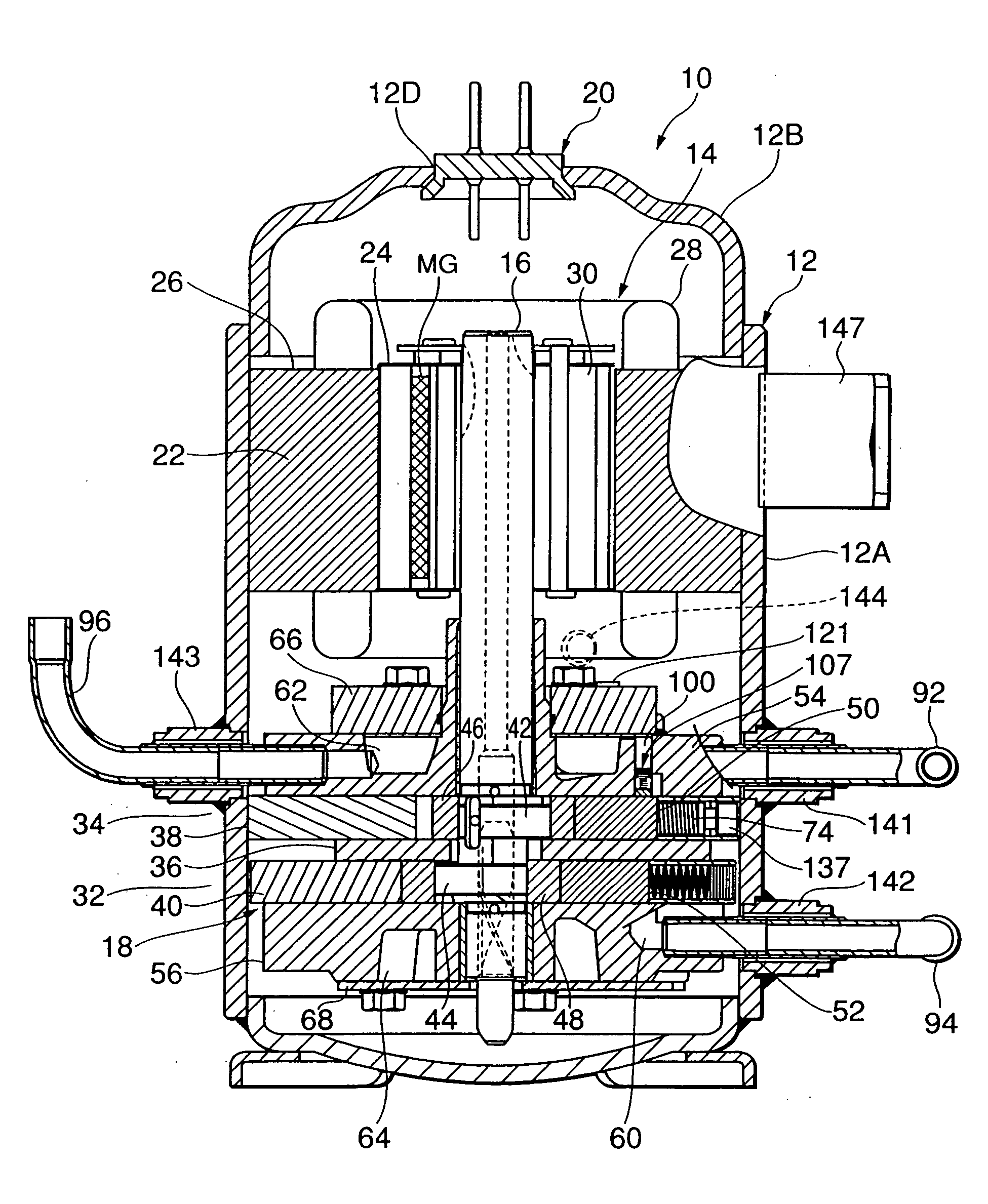
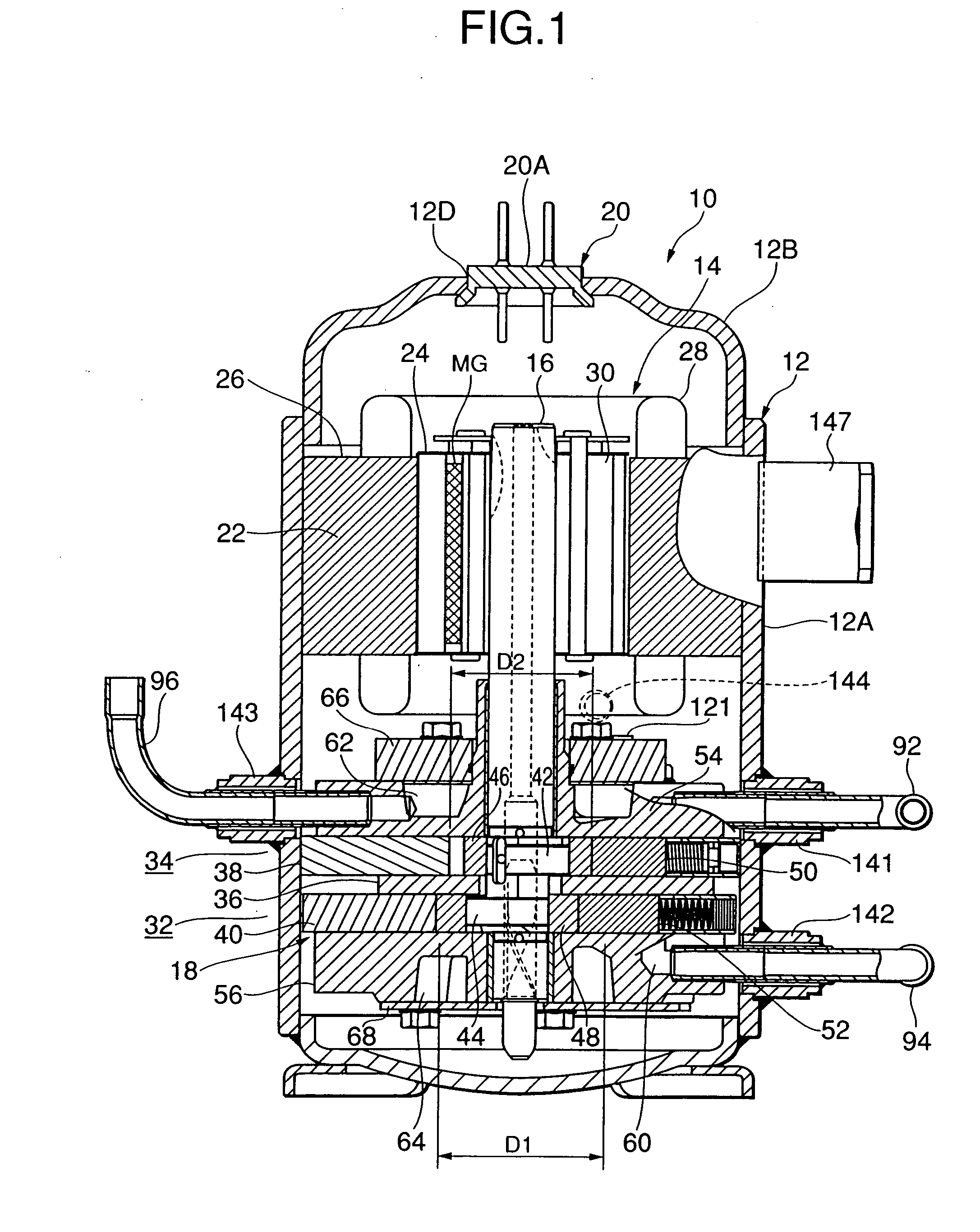
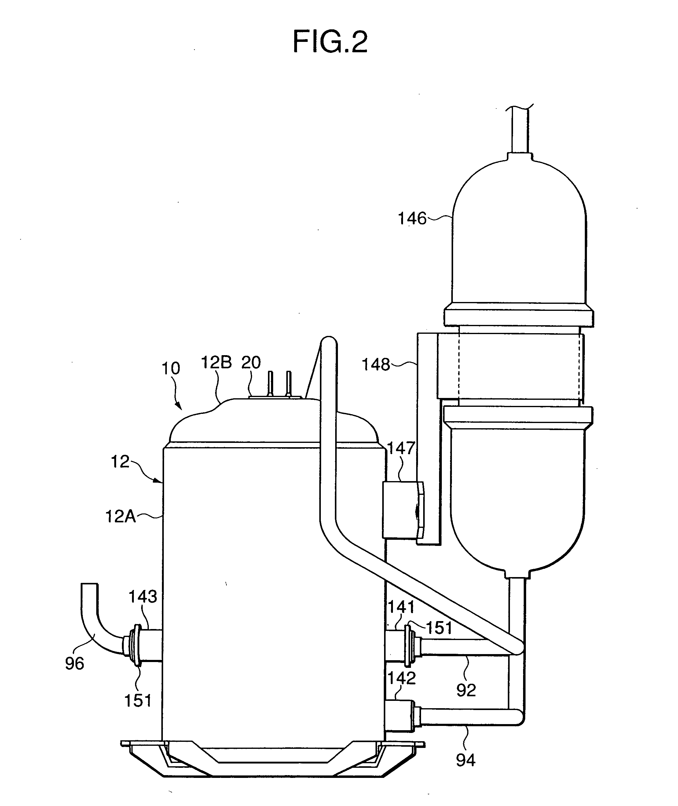
[0069] The following will detail embodiments of the present invention with reference to drawings. In figures, a reference numeral 10 indicates an internal medium-pressure, multi-stage compression type rotary compressor using carbon dioxide as a refrigerant which comprises a cylindrical sealed vessel 12 made of a steel plate and a rotary compression mechanism portion 18 which includes an electrical-power element 14 arranged and housed in an upper part of an internal space of the sealed vessel and a first rotary compression element 32 (first stage) and a second rotary compression element 34 (second stage) which are arranged below the electrical-power element 14 to be driven by a rotary shaft 16 of the electrical-power element 14. The sealed vessel 12 has its bottom used as an oil reservoir and is composed of a vessel body 12A which houses the rotary compression mechanism portion 18 and the electrical-power, element 14 and a roughly cup-shaped end cap (lid) 12B which blocks an upper pa...


PUM


Abstract

An object of the present invention is to provide a method for manufacturing a multi-stage compression type rotary compressor which can avoid the replacement of parts to be used as much as possible to reduce costs and also which enables easily setting an appropriate displacement volume ratio while preventing the compressor from being increased in size. The gist of the present invention is that an inner diameter of a lower cylinder is altered without altering its thickness (or height), and a displacement volume ratio between first and second rotary compression elements is set to an optimum value in accordance with the alteration.

Description

BACKGROUND OF THE INVENTION [0001] 1. Field of the Invention [0002] The present invention relates to a rotary compressor which compresses a refrigerant by a rotary compression element to discharge it, a method for manufacturing the same, and a defroster for a refrigerant circuit using the same. [0003] 2. Description of the Related Art [0004] Conventionally, in a multi-stage compression type rotary compressor, a refrigerant gas is sucked through a suction port of a first rotary compression element into a low-pressure chamber side of a cylinder, compressed by the operations of a roller and a vane to have a medium pressure, and discharged into a sealed vessel through a discharge port of the side of a high pressure chamber of the cylinder. Then, the refrigerant gas having the medium pressure in the sealed vessel is sucked through a suction port of a second rotary compression element into the low-pressure chamber side of the cylinder, undergoes second-stage compression through the operat...

Claims


Application Information

Patent Timeline
IPC IPC(8): F04C29/00F01C21/08F04C18/356F04C23/00F04C28/24F04C29/06F25B1/10F25B9/00F25B31/02F25B47/02
CPCF01C21/0863Y10T29/49245F04C23/001F04C23/008F04C28/24F04C29/06F04C2210/1027F04C2210/1072F04C2240/10F25B1/10F25B9/008F25B31/026F25B47/022F25B2309/061Y10T29/49236F04C18/3564F04C29/00
Inventor MATSUMOTO, KENZOYAMASAKI, HARUHISATADANO, MASAYASATO, KAZUYAMATSUURA, DAISAITO, TAKAYASUTSUDA, NORIYUKI
Owner SANYO ELECTRIC CO LTD
Learn More