Integrated, in-line bumping and exposure system

a technology applied in the field of in-line bumping and exposure system, can solve the problems of excessive oxygen diffusion back into the top layer of the resin, distribution of oxygen-contaminated components, and waste of “pre-exposure” laser beams

Active Publication Date: 2005-01-20
THE PERKIN ELMER CORP
View PDF3 Cites 43 Cited by
  • Summary
  • Abstract
  • Description
  • Claims
  • Application Information

AI Technical Summary

Benefits of technology

[0014] It is a further object of this invention to provide such a system and method which ensures the maximum amount of dissolved oxygen in a photopolymer substrate is consumed but also ensures that oxygen diffused back into the top layer of the photopolymer resin is also consumed.
[0015] This invention results from the realization that an imaged or non-imaged linear ultraviolet or near-ultraviolet lamp or light emitting diode (LED) array provides an acceptable and low cost method of photometrically consuming the dissolved oxygen within a photopolymer coated substrate as part of an in-line CTP system where the printed image is subsequently patterned by a modulated and rasterized laser beam or beams, or an array of light produced by an illuminated and re-imaged spatial light modulator array. The subject invention results from the further realization that the photochemical kinetics of the bumping process dictate in-line plate transfer system exposure methodologies that accommodate the requisite delay between the bump exposure and the pattern exposure. The subject invention also results from the realization that the bumping methodology is preferably matched to the patterning methodology to achieve a constant or near-constant delay between the bump and the pattern exposures required for best image quality.

Problems solved by technology

In addition, oxygen-contaminated components are distributed throughout the photopolymer.
This method works well for a flood bump exposure combined with a flood pattern exposure but fails when the bump simultaneously exposes the full plate area followed by a pattern exposure of the plate one section at a time.
In some respects, the “pre-exposing” laser beam can be thought of as wasted laser power due to the requirement of a more powerful laser than is required only for pattern exposure.
However, too large a temporal separation results in an excessive amount of oxygen that diffuses back into the top layer of the resin.
For high-speed plate imaging, a single backscan beam does not easily satisfy these two boundary conditions and can result in a small or non-existent exposure process window.

Method used


Image

  • Integrated, in-line bumping and exposure system
  • Integrated, in-line bumping and exposure system
  • Integrated, in-line bumping and exposure system

Examples


Embodiment Construction

[0044] Aside from the preferred embodiment or embodiments disclosed below, this invention is capable of other embodiments and of being practiced or being carried out in various ways. Thus, it is to be understood that the invention is not limited in its application to the details of construction and the arrangements of components set forth in the following description or illustrated in the drawings.

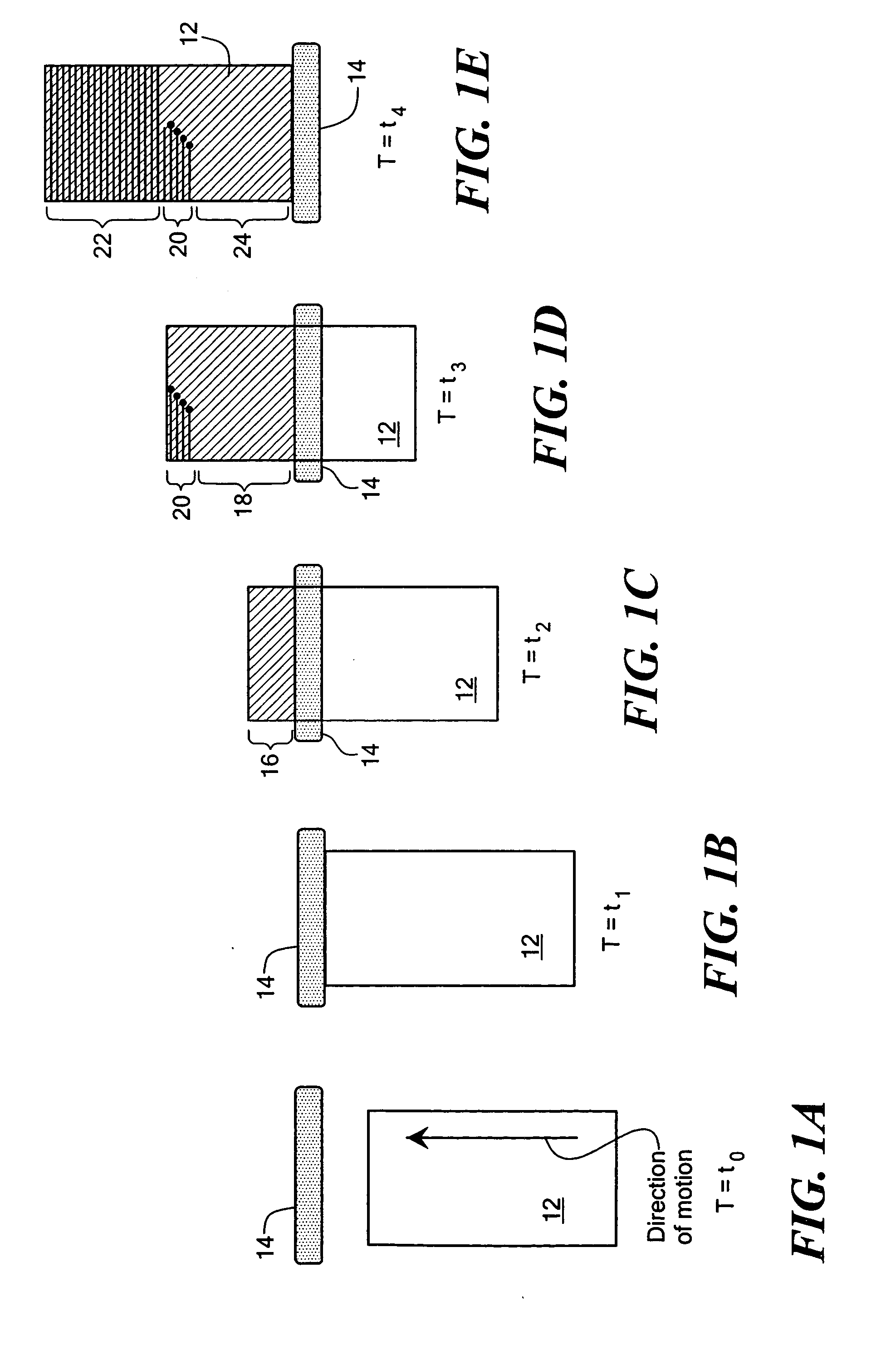
[0045] In accordance with one method of and system for the subject invention, printing plate 12, FIG. 1A, such as a flexographic plate with a photosensitive top layer is bumped by producing a band of illumination 14 across the top layer to consume any dissolved oxygen within the top photosensitive layer. Band of illumination 14 is preferably ultraviolet or near ultraviolet radiation in the range of 244-436 nm, depending upon the absorption characteristics of the resin and is produced by an ultraviolet or near ultraviolet lamp or an array of ultraviolet or near ultraviolet producing LEDs a...


PUM

PropertyMeasurementUnit
wavelengthaaaaaaaaaa
wave lengthaaaaaaaaaa

Abstract

An integrated, in-line bumping and exposure system for printing plates or other substrates having a photosensitive layer. A linear illumination source or sources are for bumping the photosensitive material with a band of illumination to consume dissolved oxygen within the photosensitive layer. A raster scan optical assembly or an illuminated and re-imaged spatial light modulator array exposes the photosensitive material with a rasterized beam or beams or an array of modulated electromagnetic radiation located downstream of the bumping illumination. A conveyance mechanism is configured to provide relative continuous motion between one or more substrates and the bands of illumination to continuously bump and pattern one portion of the plate or plates while the other portion of the plate or plates is bumped in anticipation of patterning.

Description

RELATED APPLICATIONS [0001] This application claims priority from U.S. Provisional Application Ser. No. 60 / 474,185 filed May 29, 2003.FIELD OF THE INVENTION [0002] This invention relates to an integrated, in-line bumping and exposure system for printing plates or other substrates having a photosensitive layer. BACKGROUND OF THE INVENTION [0003] Printing plates such as flexographic (flexo) plates coated with a photopolymer resin layer are typically digitally imaged or patterned using a modulated and rasterized laser beam or beams, or an array of light produced by an illuminated and re-imaged spatial light modulator array, in a machine such as a computer-to-plate (CTP) exposure system. Most flexo plates are not manufactured in an oxygen-free environment and are not overcoated with an oxygen barrier layer such as polyvinyl alcohol. In addition, oxygen-contaminated components are distributed throughout the photopolymer. In this case, there is an abundance of dissolved oxygen throughout ...

Claims


Application Information

Patent Timeline
Patent Type & Authority Applications(United States)
IPC IPC(8): B41C1/00G03B27/04G03CG03F7/20
CPCB41C1/00G03F7/2055G03F7/2022
Inventor DONAHUE, JOSEPH P.SHAVER, NORMAN L.
Owner THE PERKIN ELMER CORP
Why Eureka
Try Eureka