
Magnetic lens

Active Publication Date: 2005-01-20
FEI COMPANY
View PDF10 Cites 11 Cited by
  • Summary
  • Abstract
  • Description
  • Claims
  • Application Information

AI Technical Summary

Benefits of technology

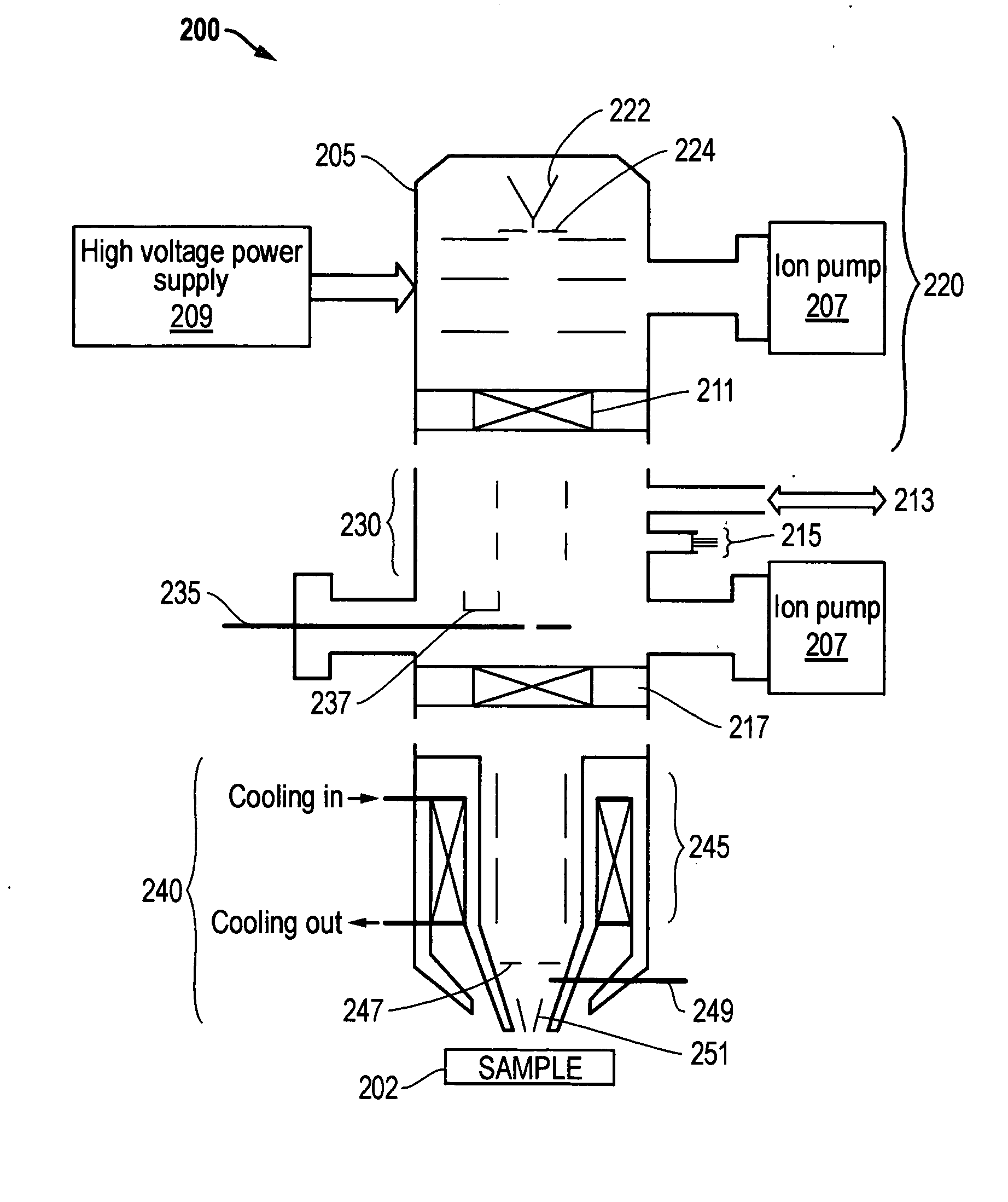
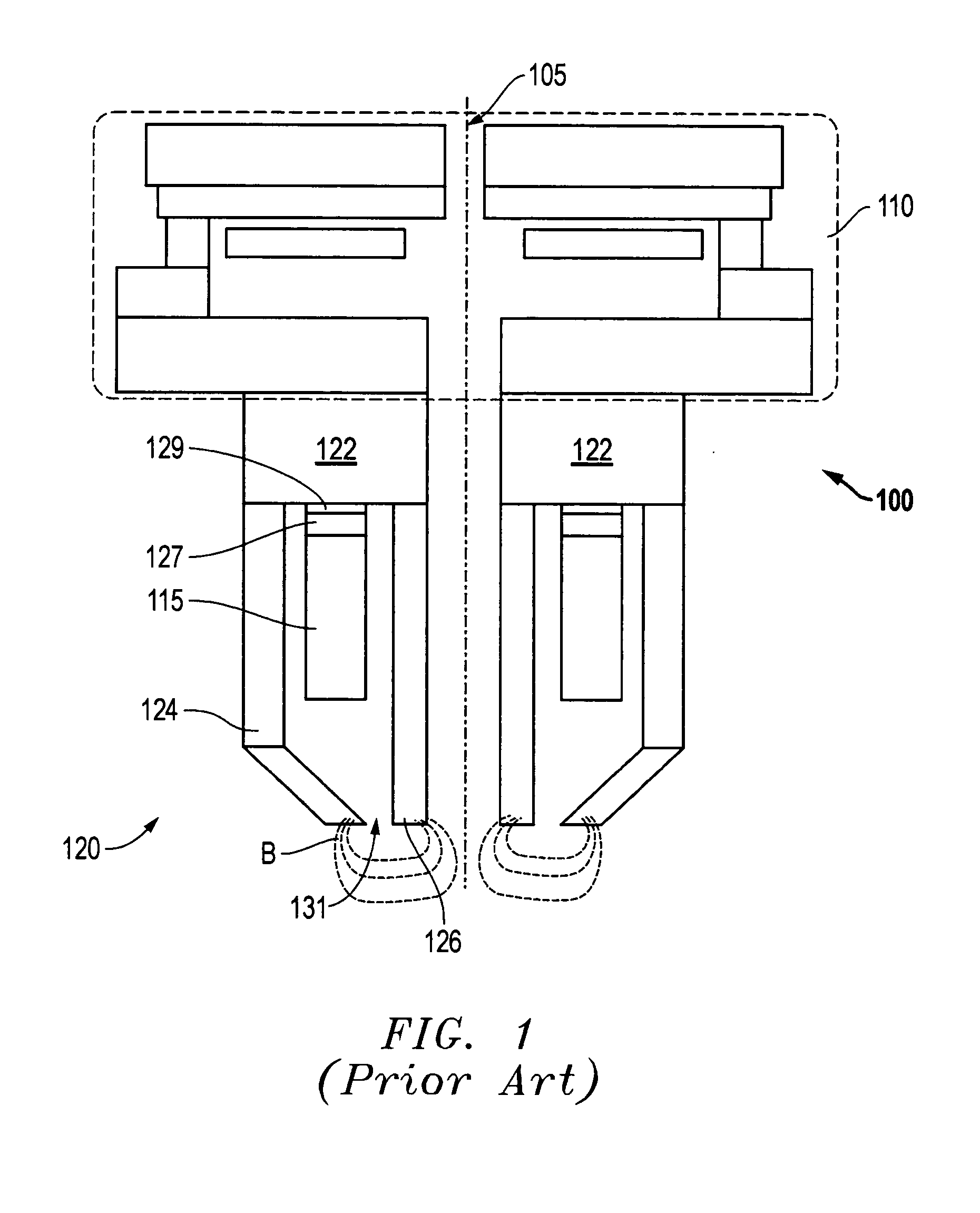
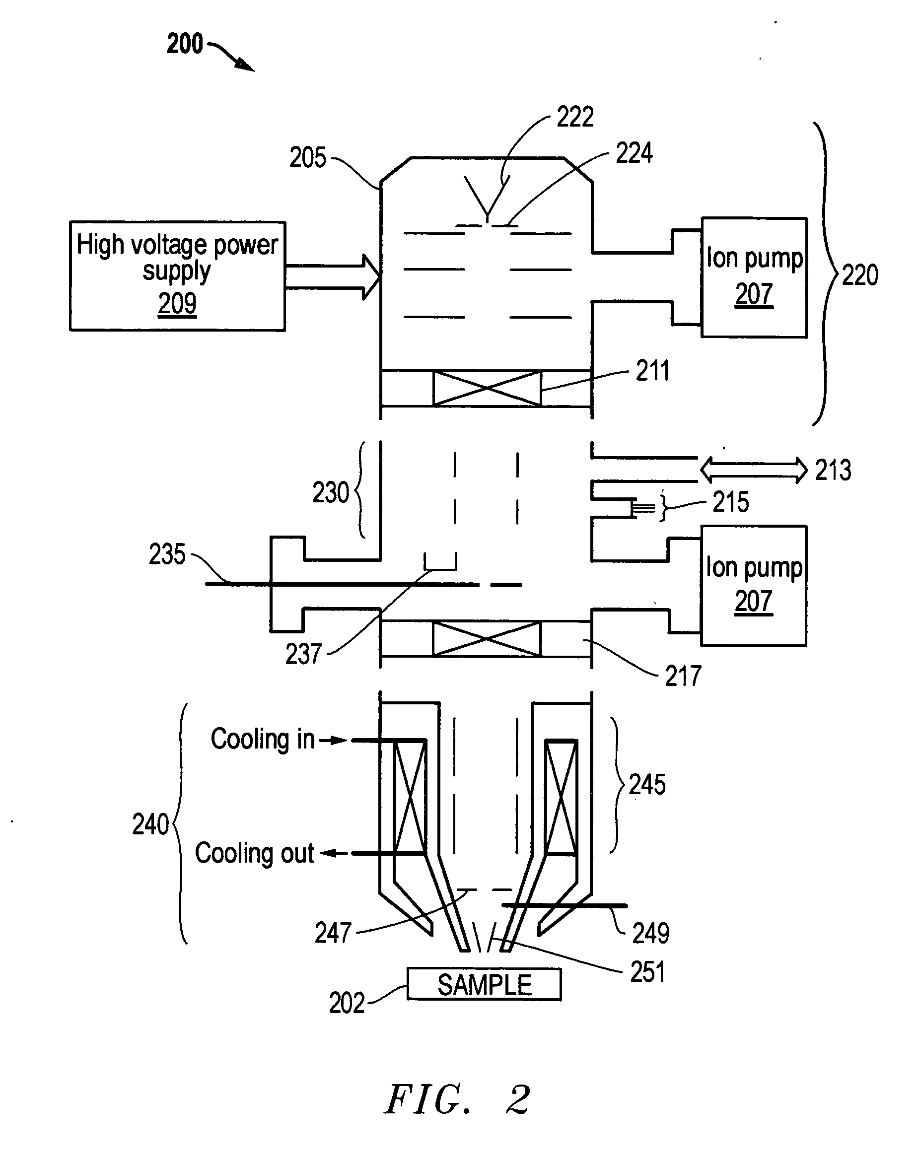
In one embodiment of the present invention, a magnetic lens is provided that can generate a substantially constant amount of average heat power over a pre-selected range of resultant magnetic field strengths. The lens is configured to do this with multiple, asymmetric (different turns) coil sections that can produce a range of desired field strengths, and at the sane time, maintain a sufficiently constant temperature signature when the average total power is maintained constant thereby eliminating unreasonable delays in lens operation when the resultant field strength is changed over the operating range of field strengths. The asymmetric lens structure allows for the smaller coil to be made with less relative inductance thereby making it more responsive and amenable for AC signal driving and thus dynamic focusing applications if desired. Thus, a magnetic lens is now provided that can produce a range of magnetic beam-focusing field strengths, implement dynamic focusing, and not impose unreasonable delay for thermal stabilization between changes in magnetic field strength.

Problems solved by technology

The heat emitted from the lens coil will raise the temperature in the lens pole assembly, which causes it to expand.
(Likewise, a decrease in field strength causes the temperature to fall and the pole assembly to contract.)
This is problematic because the exact position of the lens pole pieces with respect to each other and the centerline of the electrons define the position where the electrons are focused on the specimen.
This can impose a delay in operating the device after changing the field strength so that the lens coil has sufficient time (e.g., one to seven hours) to thermally stabilize.
Unfortunately, the reaction times of available thermal dissipation mechanisms are typically inadequate to readily keep pace with thermal changes caused by changing the strength of the magnetic field.
While the delay may be decreased, time must still be wasted waiting for the lens to “settle.”
Unfortunately, one drawback with this approach is that the overall response of the magnetic lens is fairly slow.

Method used


Image

  • Magnetic lens
  • Magnetic lens
  • Magnetic lens

Examples


example

In an exemplary dual beam system (not shown), a multi-coil lens as described above has the following characteristics:

Total number of turns:1232Turns ratio's n1:n2:n18:6:8Ampere turns1140 AtMean diameter   80 mmDynamic focus requirement (Δzfocus): ≈25 μmZfocus≈2.3 mm

Moreover, the acceleration voltage of the electron beam in an SEM must be allowed to quickly changed (interruption less than one minute) over a range of operating voltages from 500V to 2 kV. For the same focus point, this results in a required change in magnetic field from 570 to 1140 amp-turns (a change of a factor of two), and hence a variation in dissipated power of a factor 4. These parameters were met by implementing the following measures.

Consistent with the lens of FIG. 4, a circular symmetric construction was employed. The objective coil was cooled with a water-cooling body having thermally conductive side covers, and it was insulated from the SEM housing. The constant power dissipation and constant power de...


PUM


Abstract

In one embodiment of the present invention, a magnetic lens is provided that can generate a substantially constant amount of average heat power over a pre-selected range of resultant magnetic field strengths. The lens is configured to do this with multiple, asymmetric (different turns) coil sections that can produce a desired range of field strengths, and at the same time, maintain a sufficiently constant temperature signature when the average total power is maintained constant thereby eliminating unreasonable delays in lens operation when the resultant field strength is changed. The asymmetric lens structure allows for the smaller coil to be made with less relative inductance thereby making it more responsive and amendable for an AC drive signal and thus dynamic focusing applications if desired. Thus, a magnetic lens is now provided that can produce a range of magnetic beam-focusing field strengths, implement dynamic focusing, and not impose unreasonable delay for thermal stabilization between changes in magnetic field strength.

Description

TECHNICAL FIELD OF THE INVENTION The present invention generally relates to a magnetic lens and, in particular, relates to a magnetic lens having thermal power dissipation independent of the strength of its magnetic field. BACKGROUND OF THE INVENTION Magnetic lenses are generally known and are often employed to focus a beam of charged particles e.g., electrons. One major use of a magnetic lens is in analytical instruments such as electron microscopes, which utilize focused electron beams to stimulate a reaction from a sample that is being observed or analyzed. In such instruments the magnetic lens is useful as an objective, or final focusing lens. That is, the objective magnetic lens is the last focusing element prior to the beam impinging on the sample. As such, the stability of the beam position as affected by the magnetic lens is quite critical to achieve an accurate characterization of small features on the sample. FIG. 1 is a cross-sectional, schematic drawing of a convention...

Claims


Application Information

Patent Timeline
IPC IPC(8): G21K5/04G21K1/093H01J37/141H01J37/21H01J37/28
CPCH01J37/07H01J37/28H01J37/141
Inventor BIERHOFF, MARTINUS PETRUS MARIAKOOIJMAN, CORNELIS SANDER KEESSANFORD, COLIN AUGUST
Owner FEI COMPANY
Learn More