Optical scanner, and mechanism for cleaning optical scanner cover glass

Inactive Publication Date: 2005-01-20
SEIKO EPSON CORP
View PDF4 Cites 16 Cited by
  • Summary
  • Abstract
  • Description
  • Claims
  • Application Information

AI Technical Summary

Benefits of technology

The stopping member is provided for stopping the further movement of the cleaning lever at the terminal end when the cleaning lever is fully retracted inside. Therefore, the excessive movement of the cleaning lever is prevented, thereby achieving the economical movement of the cleaning lever.
The movement restriction means is provided for limiting the movement of the cleaning lever during retracting the cleaning lever inside and an engaging means is provided for engaging the movement restriction means. This structure can prevent such an event that dust and dirt attached to the cleaning member fly to the surface of the cover glass due to vibration of the cleaning lever. In addition, the engaging means composed of the concave and convex portions as mentioned above also functions as a click mechanism so that an operator can sensuously check when the cleaning lever reaches the traveling terminal position during pushing the cleaning lever. It should be noted that the number or parts can be reduced by integrally forming the engaging means to the mounting member.
The

Problems solved by technology

However, since no analytical study has been made and no reference about incident angle of 20° or less has been made in the Japanese Unexamined Patent Publication No.
S61-7818, the light deflective optical system cannot properly correct scanning line distortion.
However, it is hard to manufacture an anamorphic lens, to be used in a scanning optical system, having a wide effective range both in the scanning direction and the sub scanning direction.
This causes another problem that the degree of freedom of arrangement among a plurality of lenses is reduced.
However, the scanning angle must be small because the light beam interferes with the stationary plane mirrors when the light beam is incident on and projected to the deflective reflecting

Method used


Image

  • Optical scanner, and mechanism for cleaning optical scanner cover glass
  • Optical scanner, and mechanism for cleaning optical scanner cover glass
  • Optical scanner, and mechanism for cleaning optical scanner cover glass

Examples


first embodiment

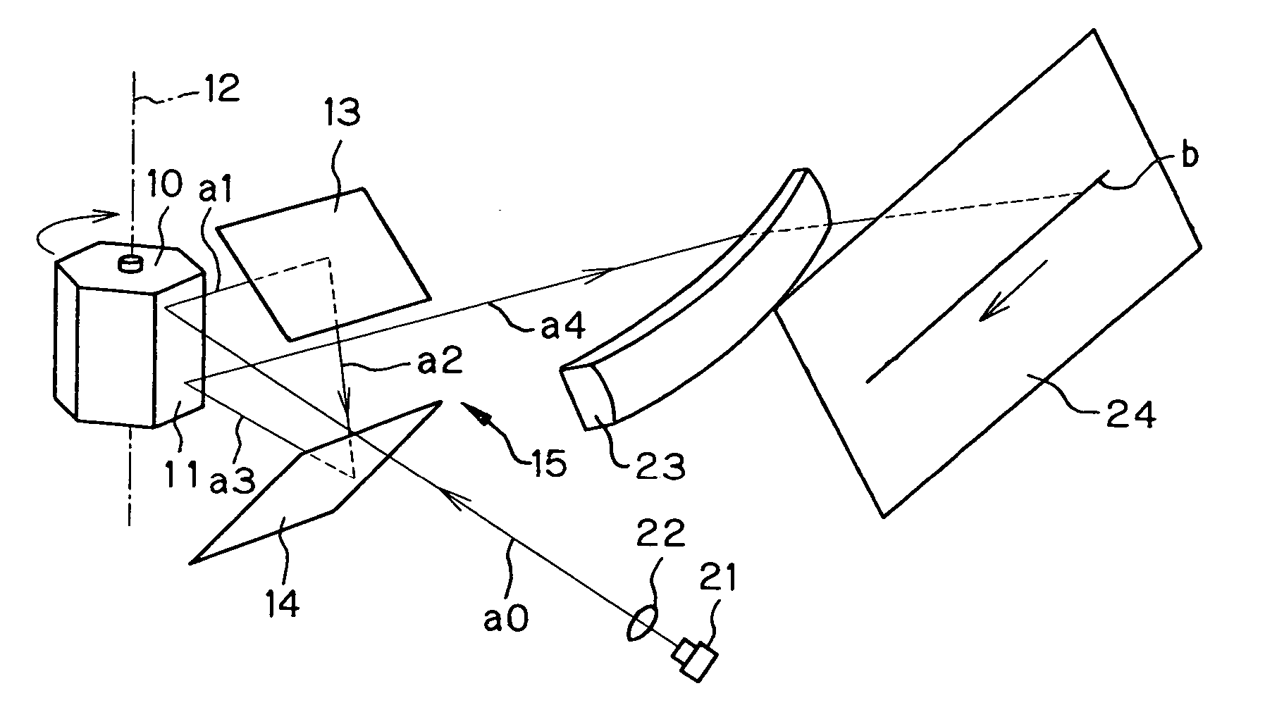
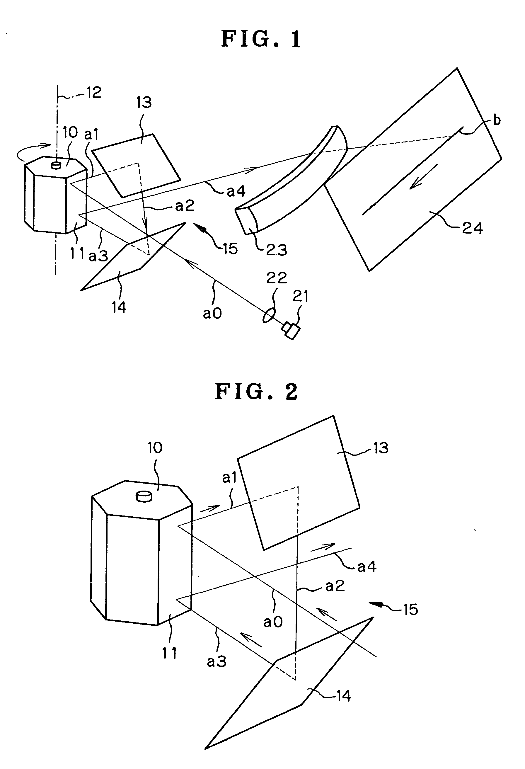
FIG. 1 is a perspective view showing the entire structure of an optical scanning device according to the present invention and FIG. 2 is a perspective view showing the light deflective optical system as main parts of the optical scanning device.

According to this structure, an optical deflector is composed of a polygon mirror 10 taking a form of a polygonal column and having a plurality (six in the illustrated example) of deflective reflecting facets 11 on the peripheral sides of the polygonal column. The polygon mirror 10 rotates about its rotational axis 12 so that the deflective reflecting facets 11 revolve about the rotational axis 12. Two stationary plane mirrors 13, 14 are disposed to face a deflective reflecting facet 11 related to optical deflection so that these plane mirrors 13, 14 have an angle relative to each other and have a space 15 therebetween.

A light beam from a light source 21 is converted into a parallel light beam a0 by a lens 22 and is incident on the deflect...

second embodiment

An optical scanning device according to the present invention will be described with reference to FIG. 18.

FIG. 18 is a perspective view showing the entire structure of the optical scanning device according to another embodiment of the present invention and FIG. 19 is a perspective view showing a light deflective optical system as main parts of the optical scanning device.

In the optical scanning device according to the first embodiment of the present invention as mentioned above, the lens with numeral 22 in FIG. 1 is a collimator lens so that the light beam converted by the lens 22 is a parallel beam which is parallel to both the direction perpendicular to and the direction parallel to the rotational axis 12. In the optical scanning device according to the second embodiment, however, a lens with numeral 22′ in FIG. 18 is an anamorphic lens. This is a point different from the first embodiment.

According to this structure, an optical deflector is composed of a polygon mirror 10 taki...


PUM


Abstract

The present invention relates to an optical scanning device in which a light beam is incident twice on a deflective reflecting facet and its object is to reduce curvature in scanning line trail or make the curvature substantially zero, or correct scanning line displacement due to the curvature in scanning line trail. Two stationary plane mirrors (13, 14) are disposed to face a deflective reflecting facet (11) which can be rotated about its rotational axis (12) such that a light beam (a1) being incident on and reflected from the deflective reflecting facet (11) is reflected by the two stationary plane mirrors (13, 14) sequentially. The reflected light beam (a3) is incident on and reflected by the deflective reflecting facet (11) again. Assuming that a plane being parallel to the rotational axis (12) and including the light beam (a0) which is first incident on the deflective reflecting facet is an incident plane, the central ray of an emergent light beam (a4) when the emergent light beam (a4) after the second reflection by the deflective reflecting facet (11) is on the incident plane and a straight line as the central ray of a light beam being projected on the incident plane when the deflective reflecting facet (11) is revolved by the maximum rotational angle are set substantially parallel to each other.

Description

TECHNICAL FIELD The present invention relates to an optical scanning device to be used for exposure for writing image of an image forming apparatus such as a laser beam printer and, more particularly, to an optical scanning device in which an optical beam is sequentially incident twice on deflective reflecting facet(s) of a rotating polygonal mirror or the like. The present invention relates to a mechanism for cleaning a cover glass of an optical scanning device which is capable of securely removing dust adhering to the surface of the cover glass. BACKGROUND ART Conventionally, an optical device comprising a deflective reflecting facet and two stationary plane mirrors has been proposed in Japanese Unexamined Patent Publication No. S51-6563. The two stationary plane mirrors are disposed to face the deflective reflecting facet which can be rotated or swivelled about its rotational axis. An incident light beam deflected by the deflective reflecting facet is reflected by the two stat...

Claims


Application Information

Patent Timeline
IPC IPC(8): G02B26/12G02B27/00
CPCG02B27/0006G02B26/129
Inventor SOWA, TAKESHIINOUE, NOZUMOMITSUI, YOICHI
Owner SEIKO EPSON CORP
Why Eureka
Try Eureka