Membrane electrode unit for electrochemical equipment

a technology of electrochemical equipment and membrane electrodes, applied in the field of electrochemical equipment, can solve the problems of affecting the design of the membrane electrode unit, the failure of the cell, and the inability to meet the requirements of the device, and achieve the effect of improving the design concep

Inactive Publication Date: 2005-01-20
UMICORE AG & CO KG
View PDF27 Cites 88 Cited by
  • Summary
  • Abstract
  • Description
  • Claims
  • Application Information

AI Technical Summary

Benefits of technology

[0018] Therefore, it was the objective of the present invention to provide a membrane electrode unit, which overcomes the disadvantages of the state of the art and, in particular, proves to be a better design concept.

Problems solved by technology

Membrane electrode units (MEUs) with projecting membrane edges are, however, susceptible to mechanical damage in production and assembly.
Such damages easily result in failure of the cell because the membrane must separate the gas spaces for the reactive gases, hydrogen and oxygen, from each other.
Membrane damage occurs particularly easily if very thin membranes (i.e., to 25 μm thickness) are used.
That causes problems in MEU production, especially for continuous processes.
Enclosing the MEU and subsequent compression can result in failure of the cell in case of damage or perforation of the membrane.
On cutting or separating the MEUs and in other subsequent process steps, there is a danger of the electrodes being short-circuited (by fibers from the gas distributor substrate, for instance).
This means that short circuits and failures can often occur in production of MEUs by the coextensive design.
The gas-tight seal between the reactive oxygen (or air) and hydrogen is another problem in the coextensive design.
That is scarcely possible because of the fine pores in the gas distributor substrates and catalyst layers.
That results in lowering of the open cell voltage (OCV) and, because of that, in a lower electrical capacity of the MEU.

Method used


Image

  • Membrane electrode unit for electrochemical equipment
  • Membrane electrode unit for electrochemical equipment

Examples


example 1

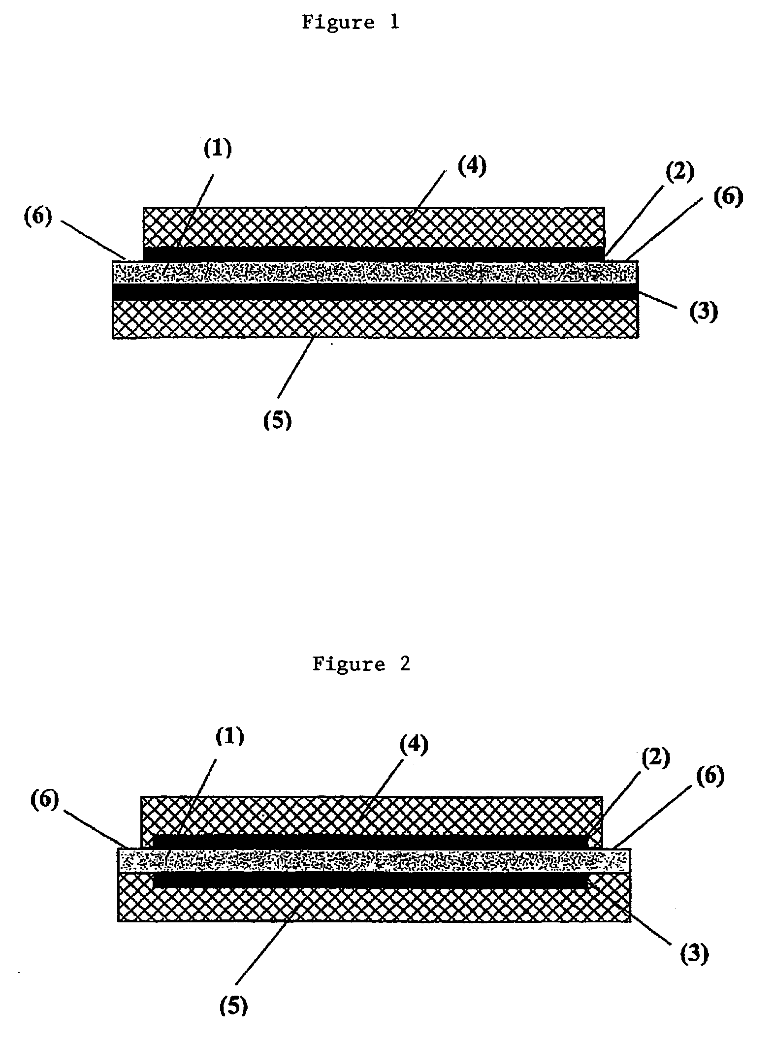
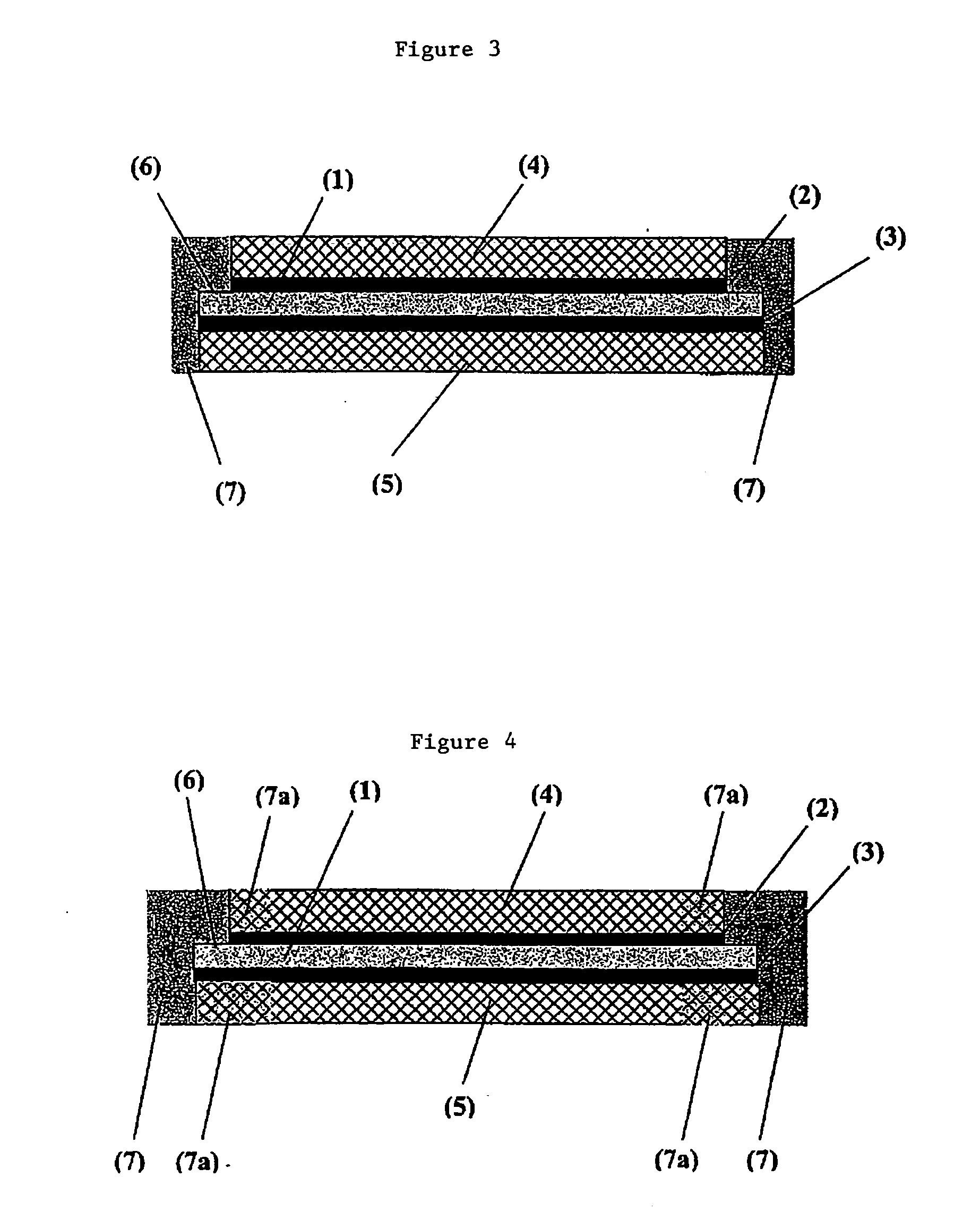
[0049] Production of a membrane electrode unit according to the invention with semi-coextensive design.

[0050] First, two catalyst-coated gas distributor substrates, each with a platinum loading of 0.25 mg Pt / cm2 are prepared. Nonwoven carbon fiber cloth of the SIGRACET 30BC type (hydrophobized, with microporous layer; SGL Co., Meitingen) is used. Special patterns are used to make [0051] a) gas distributor substrate A with dimensions of 73×73 mm; [0052] b) gas distributor substrate B with dimensions of 75×75 mm; and [0053] c) Nafion 112 (membrane (DuPont Fluoroproducts, Fayetteville, USA) with dimensions of 75×75 mm.

[0054] The gas distributor substrates A and B are positioned on the sides of the membrane with their catalyst-coated sides turned toward the membrane, and with the smaller gas distributor substrate A centered on the membrane. Then the structure is pressed at 150° C. and a pressure of 150 N / cm2. The finished membrane electrode unit has a semi-coextensive design with a 1 ...


PUM

PropertyMeasurementUnit
thicknessaaaaaaaaaa
depthaaaaaaaaaa
crystallite sizeaaaaaaaaaa

Abstract

The invention concerns a membrane electrode unit (MEU) for electrochemical equipment, especially for membrane fuel cells. The membrane electrode unit has a “semi-coextensive” design and contains an ionically conductive membrane, two catalyst layers, and gas distributor substrates of different sizes on the front and back sides. The first gas distributor substrate has smaller surface dimensions than the ionically conductive membrane, while the second gas distributor substrate has the same area as the ionically conductive membrane. The membrane electrode unit has, because of its special design, a stable structure that can be handled well, and which exhibits advantages for sealing the reactive gases off from each other and in its electrical properties. In particular, the hydrogen penetration current is distinctly reduced. The membrane electrode unit is used in PEM fuel cells, direct methanol fuel cells, electrolyzers, and other electrochemical equipment.

Description

BACKGROUND OF THE INVENTION [0001] The invention concerns the technological field of electrochemistry and describes a membrane electrode unit (“MEU”) for electrochemical equipment such as fuel cells (membrane fuel cells, PEMFC [polymer electrolyte membrane fuel cells], DMFC; etc.), electrolyzers, or electrochemical sensors. A process for producing the membrane electrode unit, and its use, are also described. [0002] Fuel cells convert a fuel and an oxidizing agent, located apart from each other at two electrodes, into electrical current, heat and water. The fuel can be hydrogen or a hydrogen-rich gas. The oxidizing agent can be oxygen or air. The process of energy conversion in the fuel cell is distinguished by a particularly high efficiency. Because of that, fuel cells combined with electrical motors are gaining importance as alternatives for the usual combustion engines. [0003] The polymer electrolyte fuel cell (PEM fuel cell) is particularly suitable for use in electric automobile...

Claims


Application Information

Patent Timeline
Patent Type & Authority Applications(United States)
IPC IPC(8): C25B9/23H01M2/00H01M2/02H01M2/08H01M2/14H01M8/10C25B9/19
CPCC25B9/10Y10T29/49115H01M4/881H01M4/8882H01M4/8896H01M8/0232H01M8/0234H01M8/0271H01M8/0273H01M8/0284H01M8/0286H01M8/1004H01M8/1023H01M8/1025H01M8/1027H01M8/103H01M8/1032H01M8/1039H01M8/1246H01M8/186Y02E60/366Y02E60/521Y02E60/528Y02E60/525Y10T29/4911Y10T29/53135Y10T29/49107H01M4/8807Y02E60/50Y02P70/50C25B9/23Y02E60/36
Inventor ZUBER, RALFSCHAACK, KLAUSWITTPAHL, SANDRADZIALLAS, HOLGERSEIPEL, PETER
Owner UMICORE AG & CO KG
Why Eureka
Try Eureka