Memory control method and memory control apparatus

Inactive Publication Date: 2005-01-20
DENSO CORP
View PDF3 Cites 5 Cited by
  • Summary
  • Abstract
  • Description
  • Claims
  • Application Information

AI Technical Summary

Benefits of technology

[0038] In this case, the access time for fetching the head address of the interrupt process routine to be activated from the interrupt address ta

Problems solved by technology

This may destroy the

Method used


Image

  • Memory control method and memory control apparatus
  • Memory control method and memory control apparatus
  • Memory control method and memory control apparatus

Examples


Example

[0048] [First Embodiment]

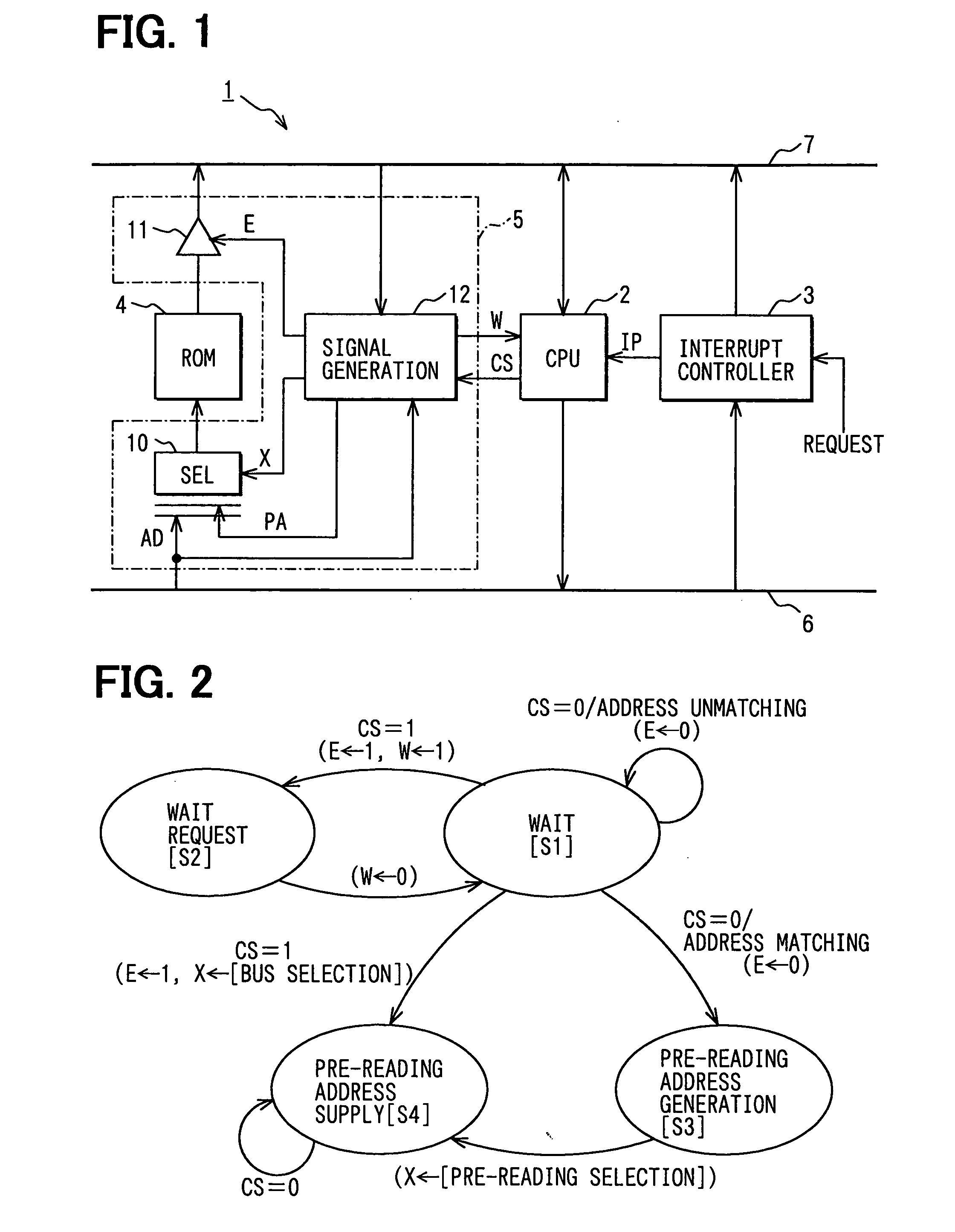
[0049] As illustrated in FIG. 1, a computer system 1 of the first embodiment comprises a central processing unit (CPU) 2 to execute pipeline process of five stages, an interrupt controller 3 for outputting an interrupt signal IP to the CPU 2 in response to an interrupt request from peripheral apparatuses not illustrated and sets also an interrupt vector number corresponding to the interrupt request to internal registers, a ROM 4 storing at least various programs to be executed by the CPU 2, interrupt process routines and an interrupt address table formed by arranging the head addresses of the interrupt process routines, and a memory control apparatus 5 to generate a wait signal W for: the CPU 2 and control access to the ROM 4 in accordance with an access request signal from the CPU 2 (for example, a chip select signal to the ROM 4). These CPU 2, interrupt controller 3, and memory control apparatus 5 are mutually connected via an address bus 6 and a data bus ...

Example

[0082] [Second Embodiment]

[0083] Next, the second embodiment will be described.

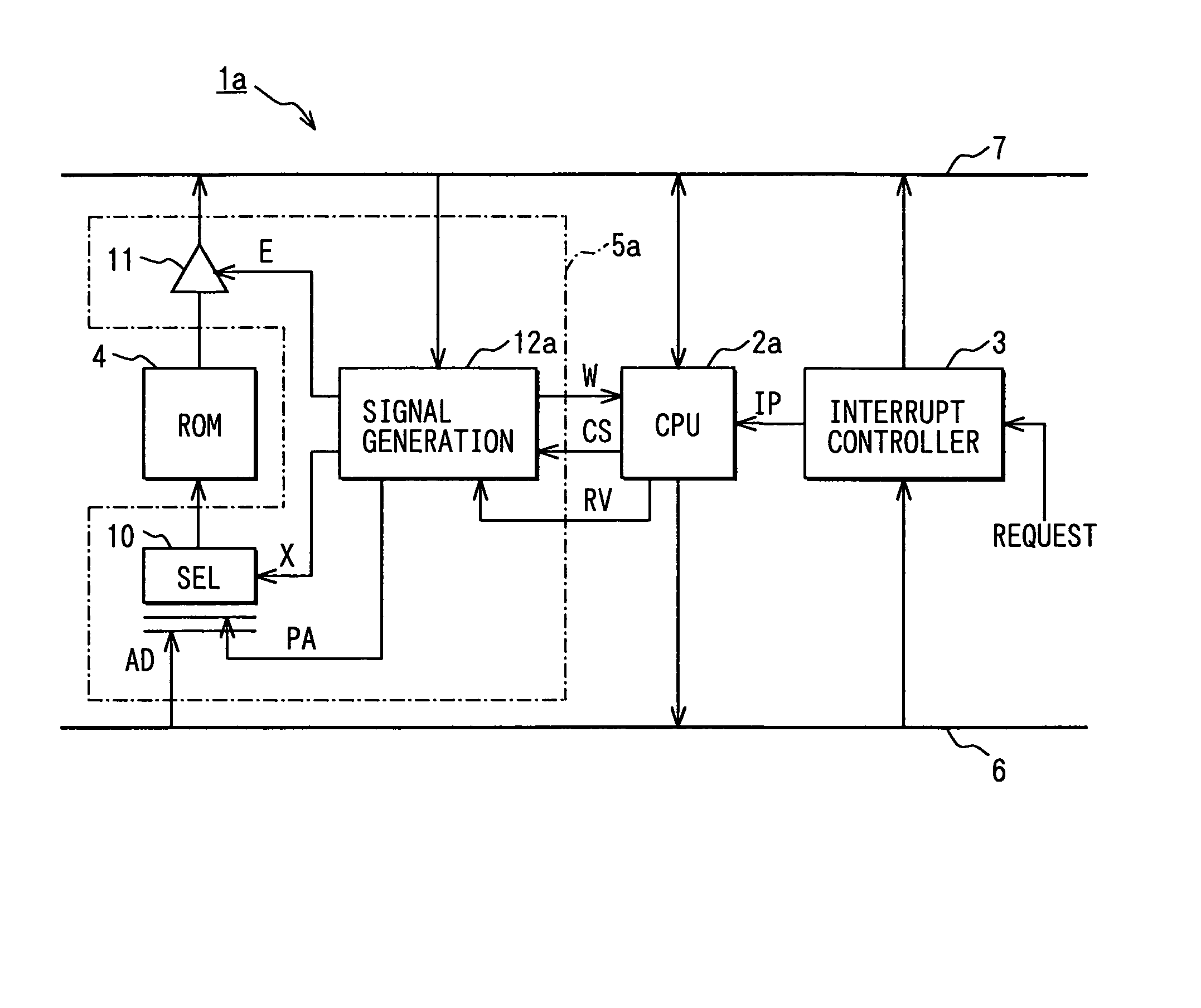
[0084] A computer system 1a of this second embodiment is different only in a part of the structure from the computer system 1 of the first embodiment. Therefore, only the different part will mainly be described.

[0085] As illustrated in FIG. 4, in the computer system 1a, a CPU 2a is configured to output, to a signal generator 12a of a memory control apparatus 5a, a stage identification signal RV which becomes active during the period of stage for reading the interrupt vector number from the interrupt controller 3.

[0086] In the first embodiment, the signal generator 12 which constitutes the memory control apparatus 5 fetches the data on the data bus 7 to generate the pre-reading address when this data matches with the address on the data bus 6. In this embodiment, however, the signal generator 12a which constitutes the memory control apparatus 5a fetches, when the stage identification signal RV is in the...


PUM


Abstract

A signal generator detects a stage in which a central processing unit (CPU) reads an interrupt vector number from an instruction controller based on an address on an address bus and generates an address of a ROM to which the CPU makes access subsequently. The generated address is defined as a pre-reading address and this pre-reading address is supplied to the ROM via a selector before the CPU starts accessing to the ROM. In this case, an output buffer is turned off. Thereafter, when the CPU starts accessing to the ROM, the selector is switched and the output buffer is simultaneously turned on so that the address on the address bus is supplied to the ROM.

Description

CROSS REFERENCE TO RELATED APPLICATION [0001] This application is based on and incorporates herein by reference Japanese Patent Application No. 2003-274831 filed on Jul. 15, 2003. FIELD OF THE INVENTION [0002] The present invention relates to a memory control method and a memory control apparatus for realizing high speed access to a memory by a central processing unit (CPU). BACKGROUND OF THE INVENTION [0003] A central processing unit (CPU) which performs a pipeline processing method is known (for example, COMPUTER ORGANIZATION & DESIGN, 1999, pp 430 to 433, by David A. Patterson; John L. Hennessy). In this CPU, the processing function to read instructions from a memory and execute the same is divided into a plurality of kinds of stages, operations of different stages are executed in parallel thereby to partially execute a plurality of instruction processing cycles in the overlapped timings. [0004]FIG. 5A is a schematic illustration of a computer system 101 which is formed with a CP...

Claims


Application Information

Patent Timeline
IPC IPC(8): G06F9/32G06F9/38G06F12/00G06F12/02G06F13/24
CPCG06F13/24
Inventor MATSUDA, TAKAYUKI
Owner DENSO CORP
Why Eureka
Try Eureka