Gas charging system for fill of gas storage and dispensing vessels

a charging system and gas storage technology, applied in the direction of positive displacement liquid engine, container discharging method, separation process, etc., can solve the problem of creating anomalous thermal effects, difficulty in single-step charging, and the inability to use the approach employed when the regulator is external to the vessel being filled

Inactive Publication Date: 2005-01-27
ADVANCED TECH MATERIALS INC
View PDF11 Cites 23 Cited by
  • Summary
  • Abstract
  • Description
  • Claims
  • Application Information

AI Technical Summary

Problems solved by technology

While such high-pressure gas storage and dispensing vessels have come into widespread usage, there are associated problems with certain industrial gases, and with specific forms of gas containment vessels.
Gases which are high boiling point gases, e.g., boron trifluoride, may condense during charging of the gas storage and dispensing vessel at high pressure levels, and create anomalous thermal effects as the charged gas expands in the vessel, due to Joule-Thompson cooling of the charged fluid.
In the filling of the interior regulator-equipped gas storage and dispensing vessels with high pressure gases, the aforementioned problems attendant Joule-Thompson cooling of the charged gas upon its expansion into the interior vessel volume, and associated thermal effects including gas liquefaction, create difficulties in single-step charging.
Because the regulator is inside the vessel, the approaches that are employed when regulators are external of the vessel being filled cannot be used.
When such approaches are attempted with an internal regulator, they are inefficient, ineffective and / or can be difficult or dangerous to implement.
Liquefied gases exiting a regulator and entering process lines cause poor regulation, over-pressurization, and the inability to control and monitor flow rates effectively.
Cascading gas fill arrangements have therefore been proposed in application to internal regulator vessels, which however are disadvantageous as requiring multiple high-pressure source vessels to fill the gas storage and dispensing vessel to increasing pressure levels.
The provision of a large number of high pressure source vessels for such purpose is undesirable from the standpoint of efficient operation and minimization of fill time, since each successive charging step in the aforementioned cascaded fill system will involve establishment of closed flow communication between the gas storage and dispensing vessel and a particular supply vessel for the period of the fill step, followed by uncoupling or disconnection of the previously coupled gas supply vessel, whereupon a new fluid flow connection must be made between the gas storage and dispensing vessel and the next succeeding gas supply vessel.
The above-discussed problems therefore limit the efficiency of the gas charging operation and necessitate additional capital expense in the provision of multiple source vessels of the high pressure gas, and the attendant requirements of piping, valving, manifolding, instrumentation, etc.
The foregoing problems, while attendant the use of internal regulator-equipped gas storage and dispensing vessels of the above-discussed type, are not limited thereto, and also are present and disadvantageous in application to a wide variety of gas storage and dispensing vessels of other and variant types.

Method used


Image

  • Gas charging system for fill of gas storage and dispensing vessels
  • Gas charging system for fill of gas storage and dispensing vessels

Examples


Embodiment Construction

[0034] The disclosures of the following U.S. Patents are hereby incorporated herein by reference in their respective entireties: U.S. Pat. No. 6,101,816 issued Aug. 14, 2000 in the names of Luping Wang and Glenn M. Tom; U.S. Pat. No. 6,089,027 issued Jul. 18, 2000 in the names of Luping Wang and Glenn M. Tom; and U.S. Pat. No. 6,343,476 issued Feb. 5, 2002 in the names of Luping Wang and Glenn M. Tom.

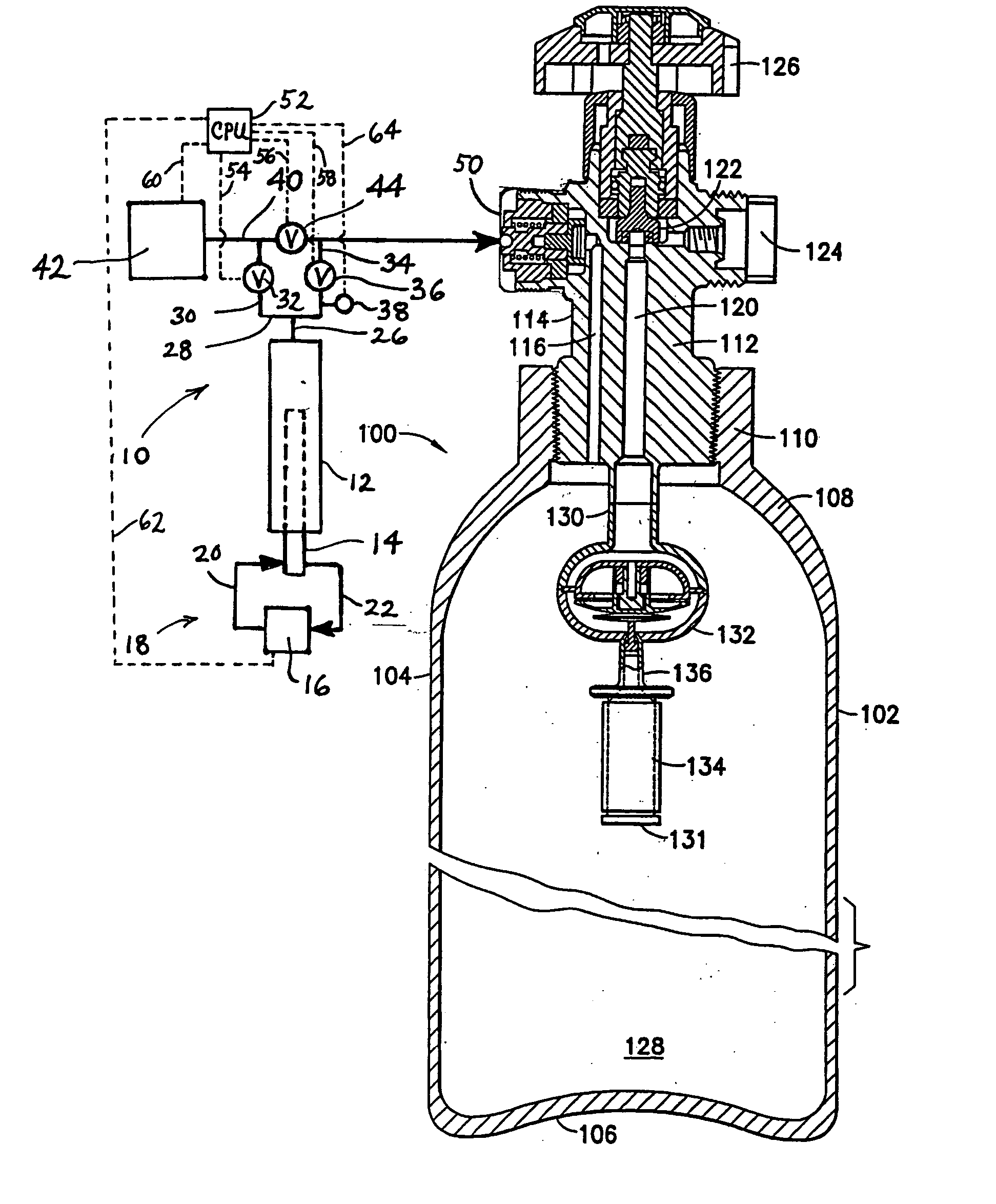
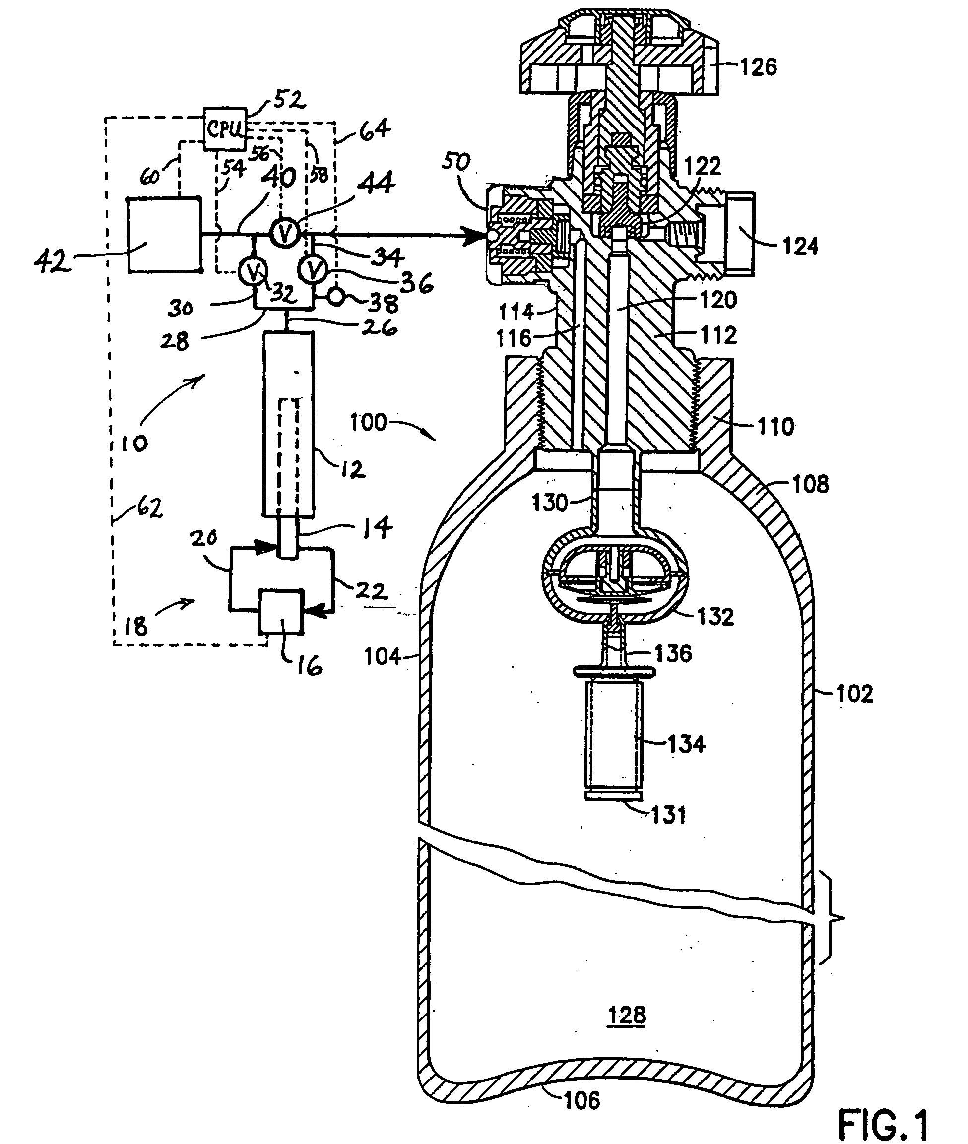
[0035] The present invention is based on the discovery that a gas storage and dispensing vessel can be rapidly and efficiently filled with high pressure gas in a simple manner using a cryotrap in a cyclic repetitive manner to effect sequential liquefaction of source gas, followed by warming of the cryotrap to allow the liquefied gas to vaporize and flow into the gas storage and dispensing vessel, with the successive liquefaction and vaporization cycles being conducted until the desired gas pressure level in the vessel is achieved.

[0036] The invention therefore utilizes cryopumping of ...


PUM

PropertyMeasurementUnit
pressuresaaaaaaaaaa
pressureaaaaaaaaaa
diameteraaaaaaaaaa

Abstract

An apparatus and method for charging a gas storage and dispensing vessel with gas to a predetermined pressure level, e.g., a gas to be employed in a semiconductor manufacturing operation such as a hydride, halide or organometallic reagent gas. In the gas charging, a source gas is liquefied, e.g., in a cryotrap, and then gasified in closed flow communication with the vessel to introduce the gas thereinto, and such liquefaction / gasification steps are carried out alternatively and repetitively, to charge the vessel in a step-wise, progressive fashion with gas, until a full fill state is achieved, with the contained gas at the predetermined pressure level.

Description

FIELD OF THE INVENTION [0001] The present invention relates generally to gas storage and dispensing apparatus and methods, and more specifically to a gas charging system that is useful to charge gas storage and dispensing vessels for holding gas at elevated pressures. DESCRIPTION OF THE RELATED ART [0002] In a wide variety of industrial processes, there is a need for compact and reliable gas supplies. Examples include semiconductor manufacturing, ion implantation, manufacture of flat panel displays, medical intervention and therapy, water treatment, emergency breathing equipment, welding operations, space-based delivery of gases, etc. [0003] In these applications, the requirement for a compact source of gas generally necessitates the deployment of pressurized gas vessels, since the inventory of available gas is maximized by correspondingly maximized pressure level of the gas in the as-furnished storage and dispensing system. As a result, it has been common practice in the gas supply...

Claims


Application Information

Patent Timeline
Patent Type & Authority Applications(United States)
IPC IPC(8): B01D8/00F17C1/00F17C5/06F17C7/00F17C7/04F17C9/02F17C13/02F17C13/04
CPCF17C1/00Y02E60/321F17C7/00F17C13/025F17C13/04F17C2201/0104F17C2201/0109F17C2201/0114F17C2201/032F17C2201/054F17C2201/056F17C2201/058F17C2203/03F17C2203/0617F17C2203/0643F17C2203/0648F17C2205/0305F17C2205/0323F17C2205/0326F17C2205/0329F17C2205/0335F17C2205/0338F17C2205/0341F17C2205/0344F17C2205/035F17C2205/0382F17C2205/0385F17C2205/0391F17C2209/221F17C2221/01F17C2221/011F17C2221/012F17C2221/014F17C2221/017F17C2221/03F17C2223/0123F17C2223/033F17C2223/035F17C2225/0123F17C2225/036F17C2227/0157F17C2227/0178F17C2227/0302F17C2227/0341F17C2227/0353F17C2227/0369F17C2227/0388F17C2227/04F17C2227/044F17C2227/047F17C2250/01F17C2250/032F17C2250/043F17C2250/0443F17C2265/05F17C2270/025F17C2270/05F17C2270/0518F17C5/06Y02E60/32
Inventor TOM, GLENN M.
Owner ADVANCED TECH MATERIALS INC
Why Eureka
Try Eureka