Control device for spark-ignition engine

a control device and spark ignition technology, applied in the direction of electric control, machines/engines, output power, etc., can solve the problems of difficulty in conventional ignition, difficulty in compression ignition, and general tendency of temperature in the combustion chamber to increase, so as to achieve efficient knocking prevention and break the effect of combustion rang

Inactive Publication Date: 2005-01-27
MAZDA MOTOR CORP
View PDF5 Cites 99 Cited by
  • Summary
  • Abstract
  • Description
  • Claims
  • Application Information

AI Technical Summary

Benefits of technology

In view of the foregoing, it is an object of the invention to provide a control device for a spark-ignition engine which makes it possible to broaden a range of combustion initiated by compression ignition to a higher-load, higher-speed side and efficiently prevent knocking in higher-load, higher-speed regions within the range of combustion initiated by the compression ignition.

Problems solved by technology

In the higher-load, higher-speed region within the compression ignition combustion range, on the other hand, there is a general tendency for the temperature in the combustion chamber to immoderately increase.
While the introduction of the cold burned gas serves to prevent knocking, it creates a tendency for the compression ignition to become difficult.
The compression ignition has not conventionally been used in relatively high-speed, high-load regions as the compression ignition, if produced, causes engine knock to occur.

Method used


Image

  • Control device for spark-ignition engine
  • Control device for spark-ignition engine
  • Control device for spark-ignition engine

Examples


first embodiment

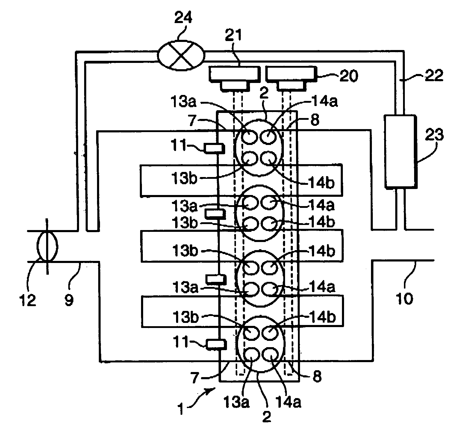
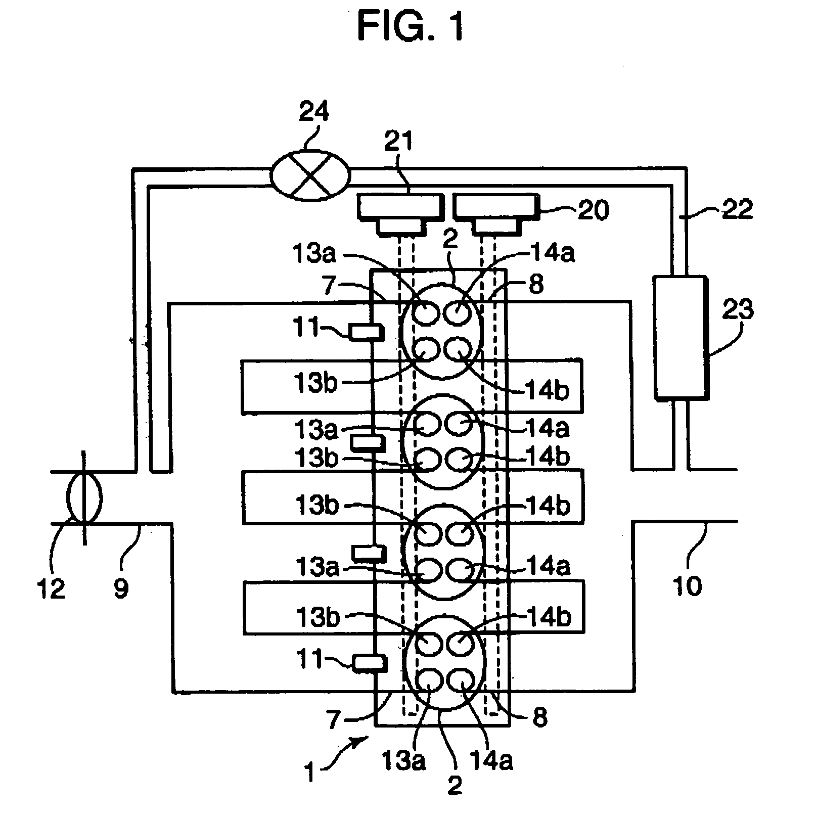
FIGS. 1 and 2 are diagrams schematically showing a spark-ignition engine incorporating a control device according to a first embodiment of the invention. As shown in these Figures, an engine body 1 has four cylinders 2 in which one each piston 3 is fitted, forming a combustion chamber 4 above the piston 3.

There is disposed a spark plug 5 at the top of the combustion chamber 4 in each cylinder 2 in such a way that a far end of the spark plug 5 is located inside the combustion chamber 4. The spark plug 5 is connected to an ignition circuit 6 which permits electronic control of ignition timing.

An intake port 7 and an exhaust port 8 open to the combustion chambers 4 of each cylinder 2, and an intake passage 9 and an exhaust passage 10 are connected to these ports 7, 8. There is provided a fuel injector 11 in each intake port 7 for injecting fuel, the fuel injector 11 incorporating a needle valve and a solenoid which are not illustrated. Driven by a later-described pulse signal input...

second embodiment

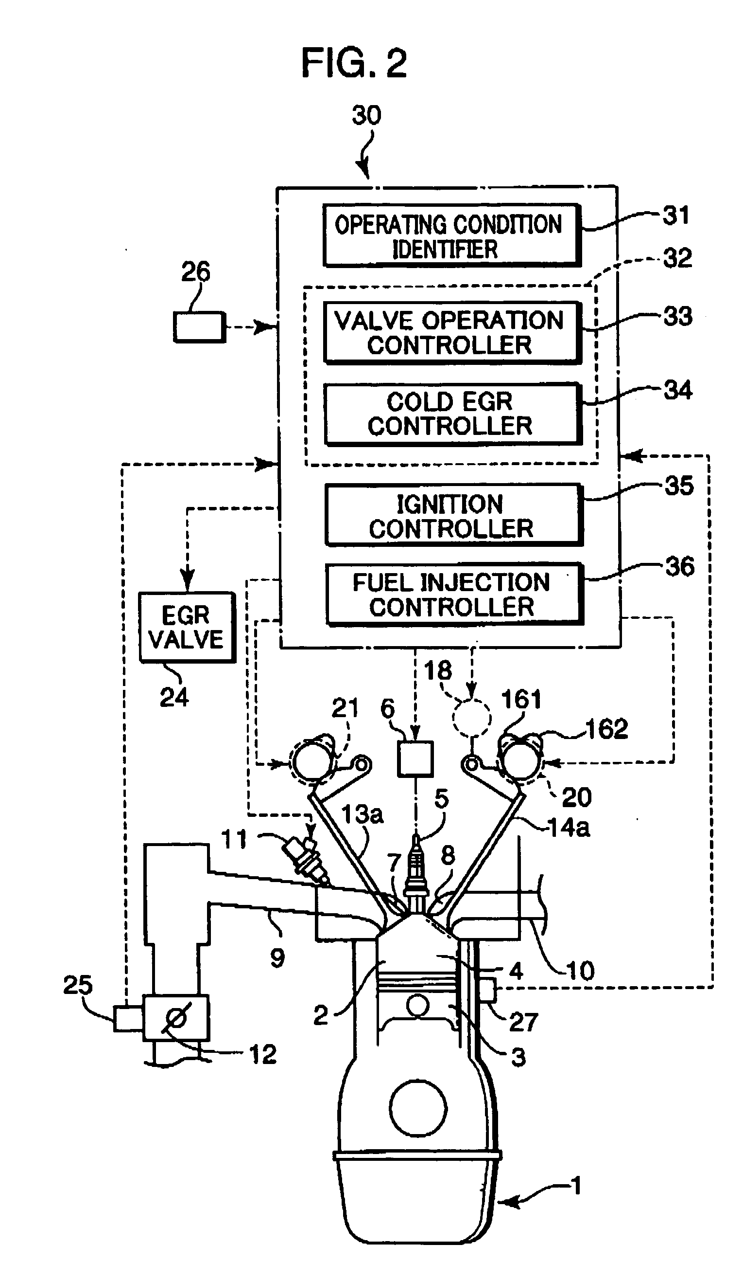
A spark-ignition engine incorporating a control device according to a second embodiment of the invention is now described referring to FIGS. 9 to 12. The engine of the second embodiment has generally the same construction as that of the first embodiment including the aforementioned valve lift varying mechanism 15. Therefore, reference should be made to FIGS. 1 to 3 for the general engine construction and those elements which are identical or similar to those of the first embodiment.

Referring to FIG. 9, the ignition circuit 6, the fuel injectors 11, the control valve 18 of the valve lift varying mechanism 15, the valve timing varying mechanisms 20, 21 and the EGR valve 24 are controlled by an ECU 40. Sensing signals output from various sensors, such as the throttle opening sensor 25 for detecting the opening of the throttle valve 12, the engine speed sensor 26 for detecting engine speed, the water temperature sensor 27 for detecting the temperature of engine cooling water and ion ...

third embodiment

A spark-ignition engine incorporating a control device according to a third embodiment of the invention is now described referring to FIGS. 13 to 19. FIGS. 13 and 14 show the general construction of the engine of this embodiment, in which an engine body 51 has a plurality of cylinders. Like the foregoing first and second embodiments, the engine body 51 has four cylinders designated 52A to 52D in this embodiment, with one each piston 53 fitted in the individual cylinders 52A-52D and a combustion chamber 54 formed above the piston 53. There is disposed a spark plug 55 at the top of the combustion chamber 54 in each cylinder 52 and the spark plug 55 is connected to an ignition circuit 56.

On one side of the combustion chamber 54 of each cylinder 52, there is provided a fuel injector 58 for injecting fuel directly into the combustion chamber 54. Although not illustrated, the fuel is supplied from a fuel pump to the fuel injector 58 through a fuel-feeding passage, a fuel-feeding system...


PUM


Abstract

A control device for a spark-ignition engine, in which a mixture in a combustion chamber is fired by compression ignition in a part-load range under warm-running conditions, includes an EGR controller incorporating a valve operation controller for controlling internal EGR of hot burned gas and a cold EGR controller for controlling external EGR of cold burned gas. The EGR controller performs EGR control operation to leave the hot EGR gas in the combustion chamber in a lower-load, lower-speed region within a compression ignition combustion range and to introduce the cold EGR gas into the combustion chamber in a higher-load, higher-speed region within the compression ignition combustion range. The control device further includes a firing assist unit for inducing the compression ignition at least when ignitability of the mixture decreases due to introduction of the cold EGR gas in the compression ignition combustion range.

Description

BACKGROUND OF THE INVENTION 1. Field of the Invention The present invention relates to a spark-ignition engine which burns an air-fuel mixture in a combustion chamber by compression ignition in a part-load range under warm-running conditions. 2. Description of the Related Art Compression ignition has intensively been studied in recent years as means for improving fuel economy in spark-ignition engines (gasoline engines). The compression ignition is spontaneous firing of a mixture in a combustion chamber occurring under high temperature and pressure conditions in a final part of a compression stroke as in a diesel engine. As the compression ignition causes the mixture to rapidly burn throughout the entire combustion chamber, the fuel economy greatly improves as a result of increased combustion efficiency. In addition, the compression ignition serves to decrease the production of nitrogen oxides (NOx), contributing thereby to an improvement in emissions. Prior art proposes an arr...

Claims


Application Information

Patent Timeline
Patent Type & Authority Applications(United States)
IPC IPC(8): F01L1/053F01L1/14F01L1/18F01L13/00F02B1/04F02B1/12F02B23/10F02D9/10F02D13/02F02D21/08F02D35/02F02D41/00F02D41/30F02F1/42F02M25/07
CPCF01L1/053Y02T10/36F01L1/185F01L13/0036F02B1/04F02B1/12F02B23/104F02D9/1095F02D13/0207F02D13/0265F02D13/0273F02D35/021F02D35/025F02D35/027F02D41/0025F02D41/006F02D41/0065F02D41/3041F02D2041/001F02D2200/0611F02F1/4214F02M25/0727F02M25/0748F02M25/0749F02M25/0752F02M25/0754Y02T10/128Y02T10/47F02D19/0636F02D19/0649Y02T10/18F01L1/143F02M26/01F02M26/23F02M26/42F02M26/43F02M26/47Y02T10/12Y02T10/30Y02T10/40
Inventor HITOMI, MITSUOHAYASHI, TAKAYOSHISUMIDA, KOUJIYAMAKAWA, MASAHISAMATSUZAKI, SATORUMAEDA, HIROYUKI
Owner MAZDA MOTOR CORP
Why Eureka
Try Eureka