Registered collimator device for nuclear imaging camera and method of forming the same

a nuclear imaging and registered technology, applied in the field of nuclear medicine, can solve the problems of difficult to machine thin septa and maintain uniform thickness, labor-intensive machining and drilling of registered square holes from blocks of lead or tungsten, and waste of materials

Inactive Publication Date: 2005-01-27
SIEMENS MEDICAL SOLUTIONS USA INC
View PDF24 Cites 33 Cited by
  • Summary
  • Abstract
  • Description
  • Claims
  • Application Information

AI Technical Summary

Problems solved by technology

Often times, a conventional hexagonal collimator is not an optimum collimation device for a discrete / pixellated scintillator system due to the geometric mismatch in terms of hole size and shape between conventional hexagonal collimator holes and square detector pixels.
However, the registered collimators consisting of square holes create other problems.
Machining and drilling of the registered square holes from a block of lead or tungsten can be labor intensive, wasteful (e.g., materials), and expensive.
It is also difficult to machine thin septa and maintain uniform thickness.
In most cases, the required septa thickness is on the order of several hundreds of micrometers and the non-uniform septa thickness is likely to generate an asymmetric system point spread response.
Moreover, precise alignment between collimator holes and individual pixellated crystals are problematic.
However, the prior art does not address issues regarding collimator fabrication difficulties and / or reflective treatment.

Method used


Image

  • Registered collimator device for nuclear imaging camera and method of forming the same
  • Registered collimator device for nuclear imaging camera and method of forming the same
  • Registered collimator device for nuclear imaging camera and method of forming the same

Examples


Embodiment Construction

[0022] In the following detailed description of the preferred embodiment, reference is made to the accompanying drawings which form a part hereof and in which is shown by way of illustrating a specific embodiment in which the invention may be practiced. This embodiment is described in sufficient detail to enable those skilled in the art to practice the invention, and it is to be understood that other embodiments may be utilized and that structural or logical changes may be made without departing from the scope of the present invention. The following detailed description is, therefore, not to be taken in a limiting sense, and the scope of the present invention is defined by the appended claims.

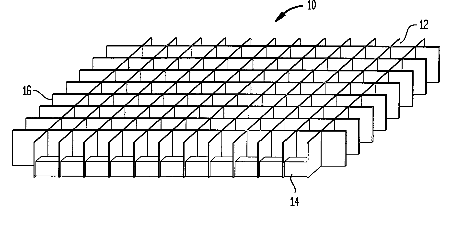
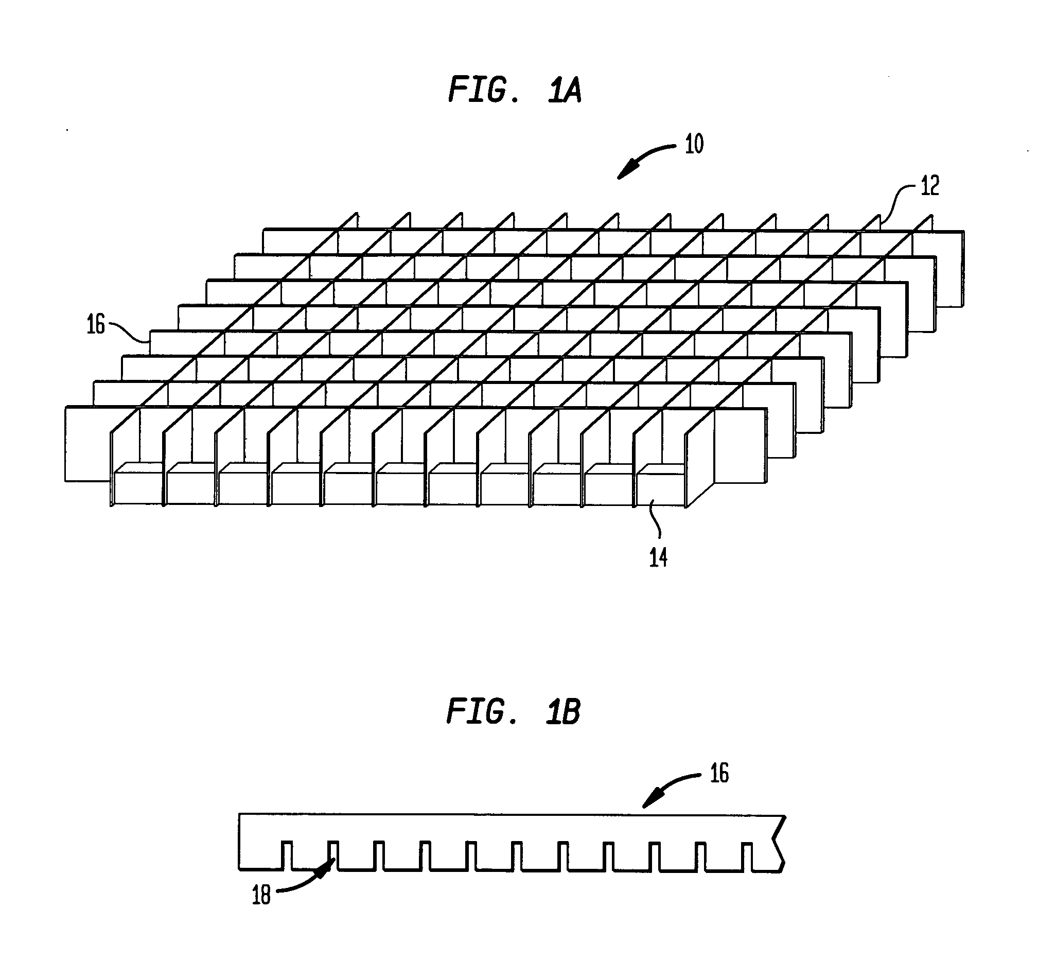
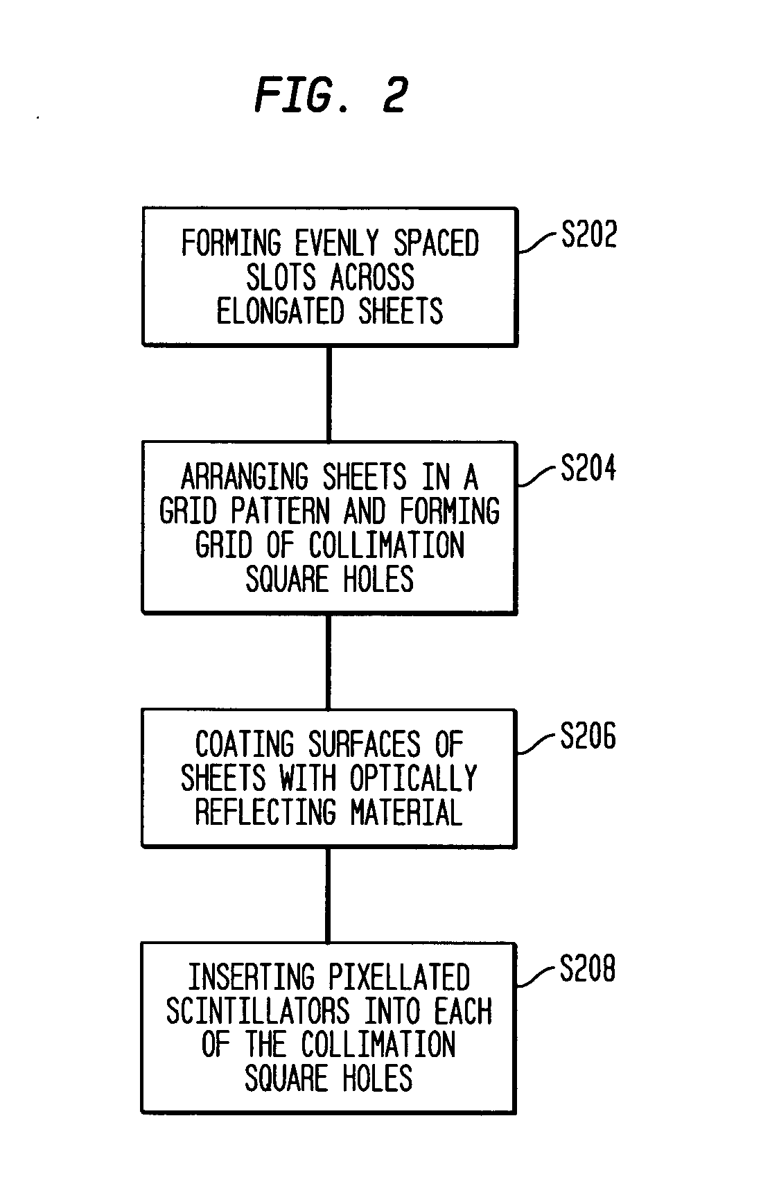
[0023]FIG. 1A schematically shows a collimator device according to an exemplary embodiment of the present invention. Referring to FIG. 1A, according to one preferred embodiment of the invention, a collimator device 10 for a nuclear imaging camera comprises a grid of collimation square holes 12...


PUM


Abstract

A collimator device for a nuclear imaging camera has a grid of collimation square holes formed by a plurality of elongated, metal sheets arranged in a grid pattern, and pixellated scintillators individually located in each of the collimation square holes. Each of the metal sheets has evenly spaced slots into which other sheets are inserted. At least a portion of the surfaces of the sheets forming the grid of the collimation square holes is coated with an optically reflecting material coating.

Description

BACKGROUND OF THE INVENTION [0001] 1. Field of the Invention [0002] The present invention generally relates to nuclear medicine, and systems for obtaining nuclear medicine images of a patient's body organs of interest. In particular, the present invention relates to a novel registered collimator device for a nuclear imaging camera and a method of forming the same. [0003] 2. Description of the Background Art [0004] Nuclear medicine is a unique medical specialty wherein radiation is used to acquire images that show the function and anatomy of organs, bones or tissues of the body. Radiopharmaceuticals are introduced into the body, either by injection or ingestion, and are attracted to specific organs, bones or tissues of interest. Such radiopharmaceuticals produce gamma photon emissions that emanate from the body. One or more detectors are used to detect the emitted gamma photons, and the information collected from the detector(s) is processed to calculate the position of origin of the...

Claims


Application Information

Patent Timeline
Patent Type & Authority Applications(United States)
IPC IPC(8): G01T1/164G01T1/20G21K1/02
CPCG21K1/025G01T1/1648
Inventor JOUNG, JINHUNCHOWDHURY, SAMIR
Owner SIEMENS MEDICAL SOLUTIONS USA INC
Why Eureka
Try Eureka