Active edge gripping end effector

a technology of end effector and active edge, which is applied in the direction of gripping heads, thin material handling, load-engaging elements, etc., can solve the problems of particle contaminants, surface damage of workpieces, damage to wafers, etc., and achieves the effect of reducing the initial impact of the gripping mechanism on the wafer, reducing the large impact force, and controlling the speed of the gripping mechanism

Active Publication Date: 2005-01-27
BOOKS AUTOMATION US LLC
View PDF17 Cites 35 Cited by
  • Summary
  • Abstract
  • Description
  • Claims
  • Application Information

AI Technical Summary

Benefits of technology

[0015] Yet another aspect of the present invention is to provide an end effector that may approach the wafer from above and pick up the wafer. The gripping surfaces of the wafer are vertical (e.g., the peripheral edge of wafer). The force feedback system ensures that the force exerted by the gripping mechanism on the wafer is sufficient to prevent the wafer from falling off the end effector.
[0016] Still another aspect of the present invention is to provide an end effector that minimizes the initial impact the gripping mechanism places on the wafer. Controlling the speed of the gripping mechanism as it approaches t

Problems solved by technology

With many workpieces, and certainly with semiconductor wafers, the surfaces of the workpieces can be easily damaged if the wafer-handling robot contacts the top or bottom surface of the wafer.
If a robot moves a wafer too abruptly, or rotates the wafer blade too fast, the wafer may slide off the blade, potentially damaging the wafer.
Further, particle contaminants may result if the wafer slides around on

Method used


Image

  • Active edge gripping end effector
  • Active edge gripping end effector
  • Active edge gripping end effector

Examples


Embodiment Construction

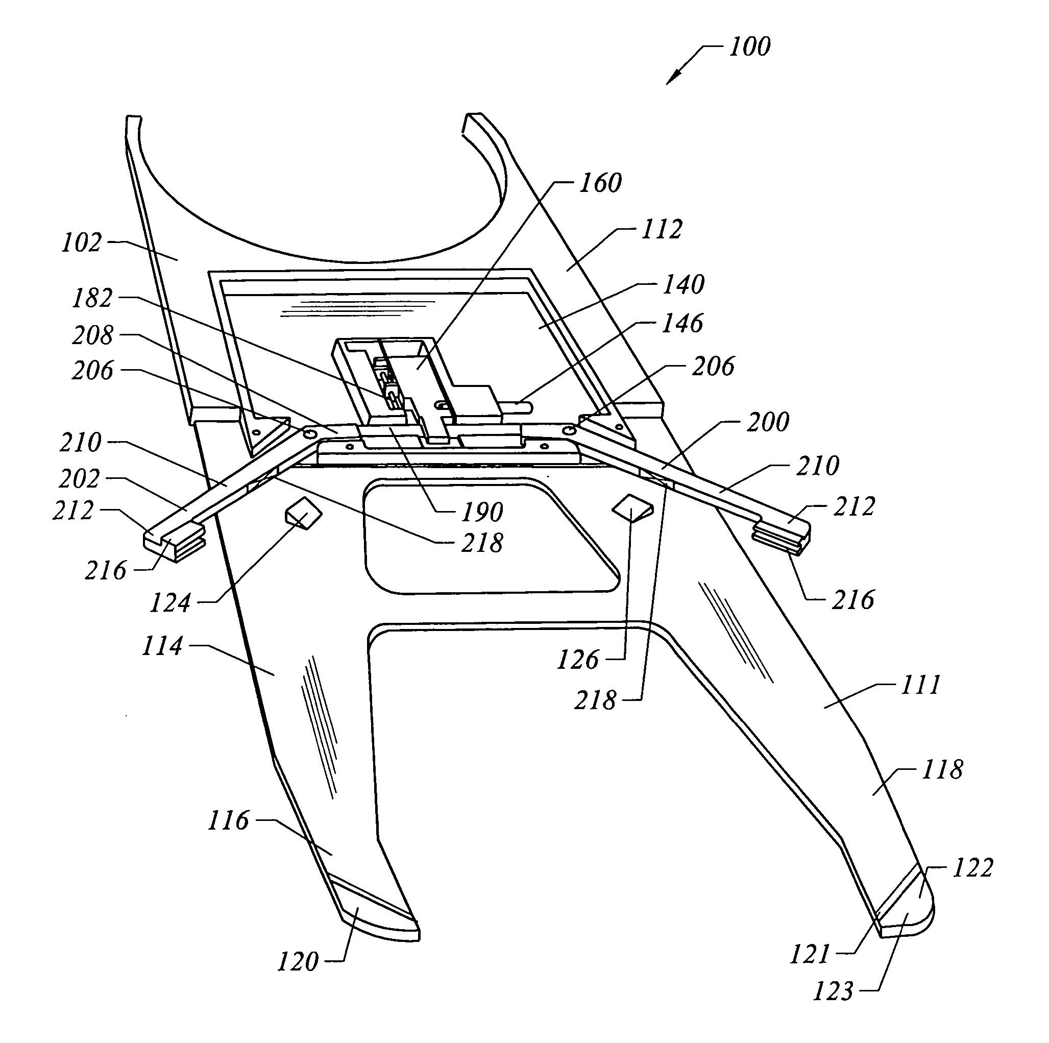
[0031] An end effector 100 manufactured according to one or more embodiments of the present invention will now be described with reference to FIGS. 2-13. In general, the end effector 100 includes a gripping mechanism that contacts the peripheral edge of a wafer in order to secure the wafer to the end effector 100.

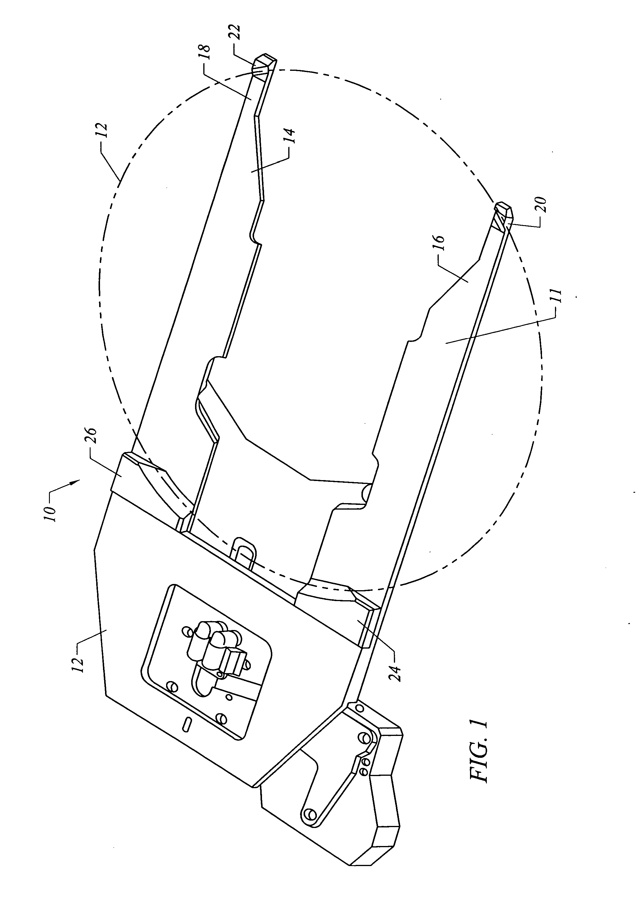
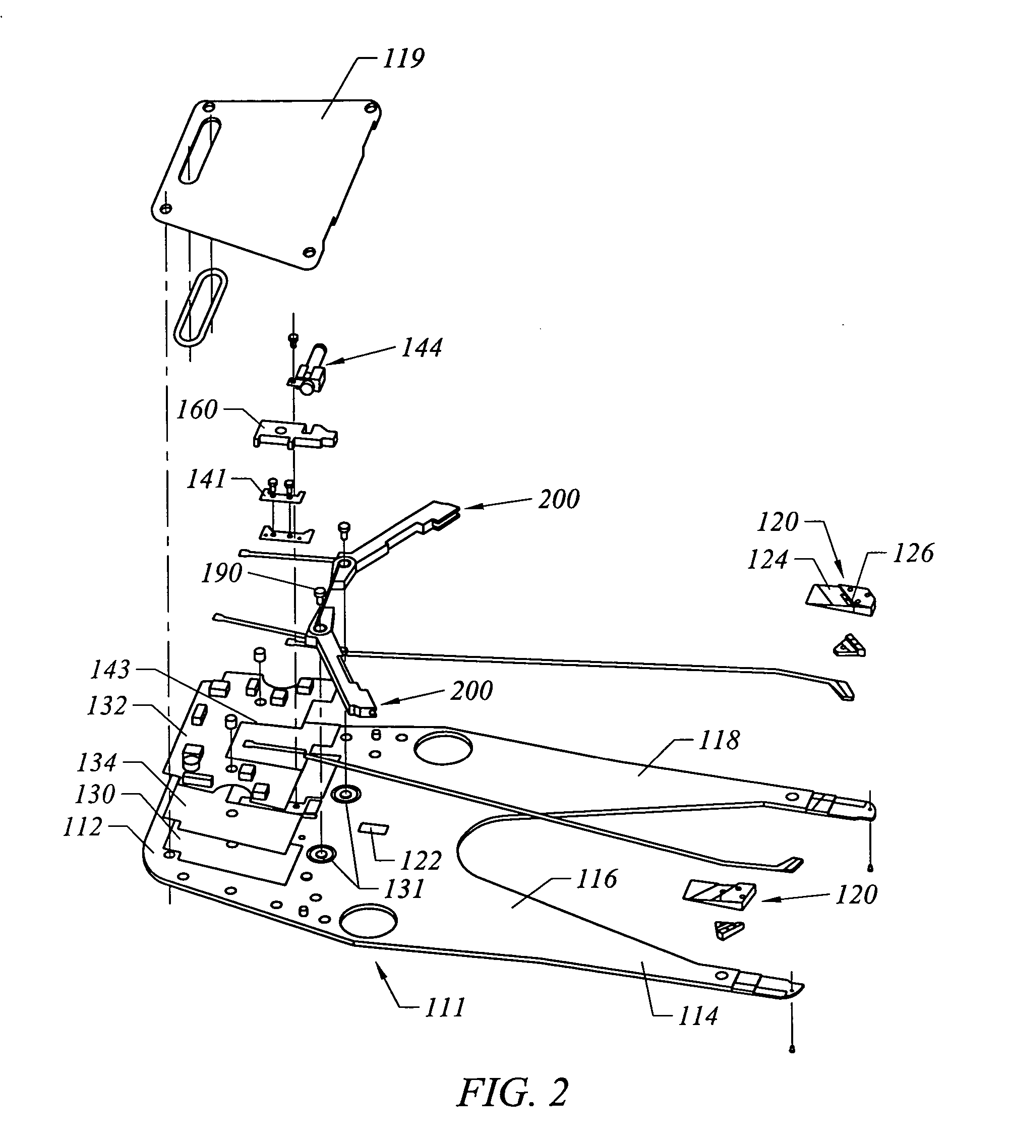
[0032]FIGS. 2-4 illustrate one embodiment the end effector 100. In this embodiment, the end effector 100 has a proximal end 112 and a distal end 114. The distal end 114 of the end effector 102 comprises a wafer blade 111 having two spaced apart fingers 116 and 118. The distal end of the two fingers 116 and 118 each include a wafer support pad 120 for supporting a portion of a wafer 12 seated on the wafer blade. It is within the scope and spirit of the invention for the wafer blade 111 to comprise a single finger in order to provide a narrower end effector. The wafer blade 111 also includes a proximal wafer support 122 so that a wafer seated on the wafer blade 111 is suppor...


PUM


Abstract

The present invention generally relates to an end effector that utilizes a gripping mechanism to grip a peripheral edge of the wafer and secure the wafer to the end effector. In one embodiment, the gripping mechanism includes a pair of gripper arms that pivot between a wafer-loading position and a wafer-engaging position. In another embodiment, an active plunger moves linearly between the wafer-loading and wafer-engaging positions. Both the gripper arms and the plunger device are driven by a motor assembly. A force feedback system monitors the force the gripping mechanism exerts on the wafer and, based on the amount of force, controls the operation of the motor assembly to dynamically adjust the position of the gripping mechanism.

Description

FIELD OF THE INVENTION [0001] The present invention generally relates to an end effector for acquiring and transporting semiconductor wafers. More particularly, the present invention comprises an end effector that includes a mechanical actuator having the ability to vary the gripping force exerted by a gripping mechanism on a wafer. BACKGROUND OF THE INVENTION [0002] Various types of wafer-handling robots are known for transporting the wafers to and from the FOUP and among processing stations. Many such robots employ a robotic arm having a spatula-shaped end that is inserted into the cassette to remove or insert a wafer. The spatula-shaped end of the robotic arm is commonly referred to as an end effector. One type of end effector secures the wafer contact surface to the wafer by a vacuum source. The vacuum source pulls the bottom surface of the wafer into contact with the entire wafer contact surface. [0003] With many workpieces, and certainly with semiconductor wafers, the surfaces...

Claims


Application Information

Patent Timeline
IPC IPC(8): B25J13/08B25J15/10H01L21/687
CPCB25J13/085B25J15/10Y10S294/907Y10S414/141H01L21/68707
Inventor ROGERS, THEODORE W.HAMILTON, SHAWN M.MAYO, MICHAEL J.
Owner BOOKS AUTOMATION US LLC
Why Eureka
Try Eureka