Dynamic diffractive optical transform

a technology of optical transform and dynamic diffractive wavefront, applied in the field of dynamic diffractive optical transform, can solve problems such as significant diffraction

Inactive Publication Date: 2005-01-27
BIRDWELL WILLIAM A
View PDF72 Cites 30 Cited by
  • Summary
  • Abstract
  • Description
  • Claims
  • Application Information

AI Technical Summary

Benefits of technology

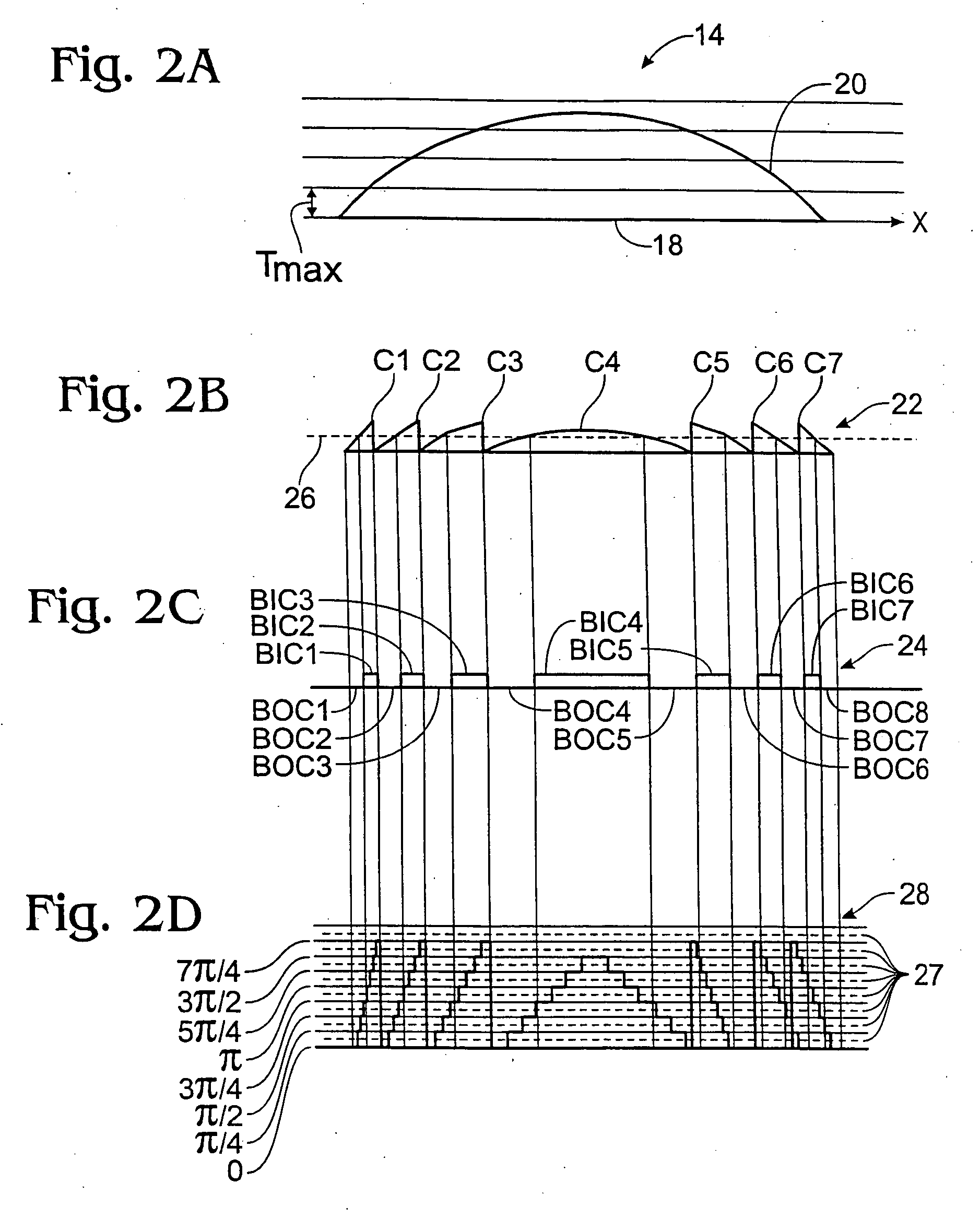
Preferably, the transform comprises one or more cells comprising the body of material and having transparent electrodes arranged in a predetermined pattern on opposing interior faces of each cell and selectively driven by a circuit which thereby produces the desired electric field pattern. The electrodes may be driven so as to produce an arbitrary transmission property pattern, or a transmission property pattern which approximates the shape of a Fresnel lens-like construct or is quantized to produce a multiple-level representation of the construct. Preferably, the electrodes effectively partition the body of material into divisions whose proportions relative to the wavelength of light result in significant diffraction. Also, preferably, the body of material comprises liquidcrystal material. Further, a multiple-level phase delay embodiment preferably employs at least sixteen phase delay levels so as to produce high diffraction efficiency.
It is yet another object of the present invention to provide a dynamic optical transform which can produce an arbitrary diffraction pattern.

Problems solved by technology

Preferably, the electrodes effectively partition the body of material into divisions whose proportions relative to the wavelength of light result in significant diffraction.

Method used


Image

  • Dynamic diffractive optical transform
  • Dynamic diffractive optical transform
  • Dynamic diffractive optical transform

Examples


Embodiment Construction

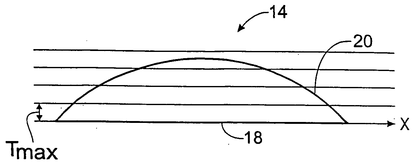
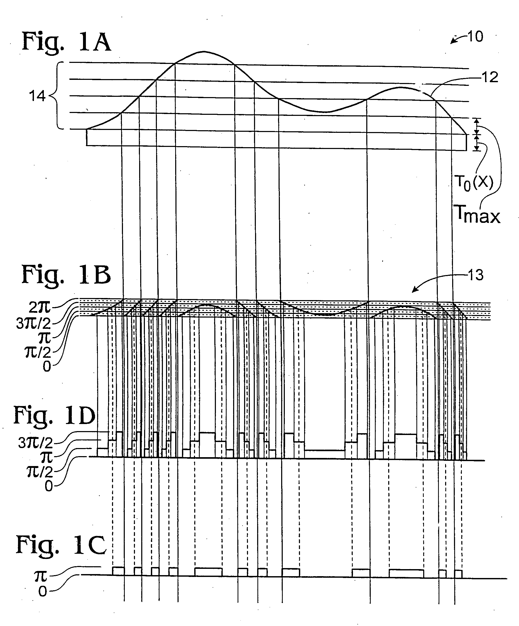
Turning first to FIG. 1A, an arbitrary optical transform is represented by a corresponding arbitrary optical element 10 of uniform index of refraction having a profile 12 along an axis x, the profile 12 representing the thickness of-the element. Since the thickness of an optical element is typically much greater than the wavelength λ of light in the medium of the element, an amount of material under the profile 12 equal in thickness to some positive integer number of wavelengths of light (2πN radians, where N is a positive integer) can be removed from the element and the remainder lowered, yet the element will have substantially the same effect on that wavelength of light. That is, an element having a profile according to the following equation would produce the same result:

T(x)=T0(x)+F(x) (mod Tmax)

where T(x)=the thickness of the element with respect to the x axis, T0(x)=the thickness of the base of the element, F(x)=the shape profile 12 in FIG. 1A with respect to the x axis, ...


PUM

PropertyMeasurementUnit
voltageaaaaaaaaaa
focal lengthaaaaaaaaaa
electric potentialaaaaaaaaaa

Abstract

A dynamic diffractive optical transform. An electric field pattern is created across a body of material, the material being characterized in that it has an optical transmission property which varies in response to of an electric potential applied across a portion thereof. The electric field pattern is created such that the resulting profile of the transmission property is an arbitrary shape which produces a desired diffraction pattern that may not be physically realizable in conventional refractive optics or is a Fresnel lens-like construct derived from a refractive optical element. This is done by selectively applying electric potentials to transparent electrode pairs having liquid crystal material therebetween and preferably relatively small proportions in relation to the relevant wavelength of light, so as to create variations in phase delay that are aperiodic, have other than fifty percent spatial duty factor or have multiple levels of phase delay. The transform is embodied in an optical scanner, an adaptive lens, and an optical switch.

Description

Background of the Invention This invention relates to devices and methods for transforming an optical wavefront in accordance with a predetermined transfer function, and particularly to a device and method for selectively transforming an optical wavefront using principles of diffractive optics. Optical transform devices of various types are commonly employed in optical systems. They work by modifying the wavefront of incoming light in a predetermined way to produce a new wavefront. In mathematical terms, this may usually be thought of as a mapping of one space by which the incoming wavefront is described to another space by which the new wavefront is described. One common optical transform device is a lens with two convex spherical surfaces. Such a lens can be used to focus an incoming wavefront to a point. Mathematically, it performs a Fourier transform on the incoming wavefront. Two other common optical transform devices are mirrors, which can be used to deflect or focus a wavef...

Claims


Application Information

Patent Timeline
Patent Type & Authority Applications(United States)
IPC IPC(8): G02F1/29G02F1/31
CPCG02F1/292G03H2225/32G03H2222/32G02F1/31
Inventor BIRDWELL, WILLIAM A.
Owner BIRDWELL WILLIAM A
Why Eureka
Try Eureka